What Does a Double Isolation Dual-Power Vacuum Circuit Breaker Do?
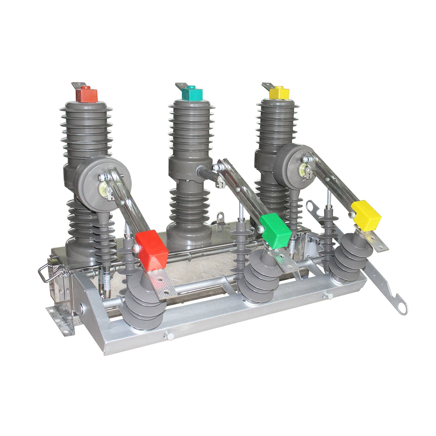
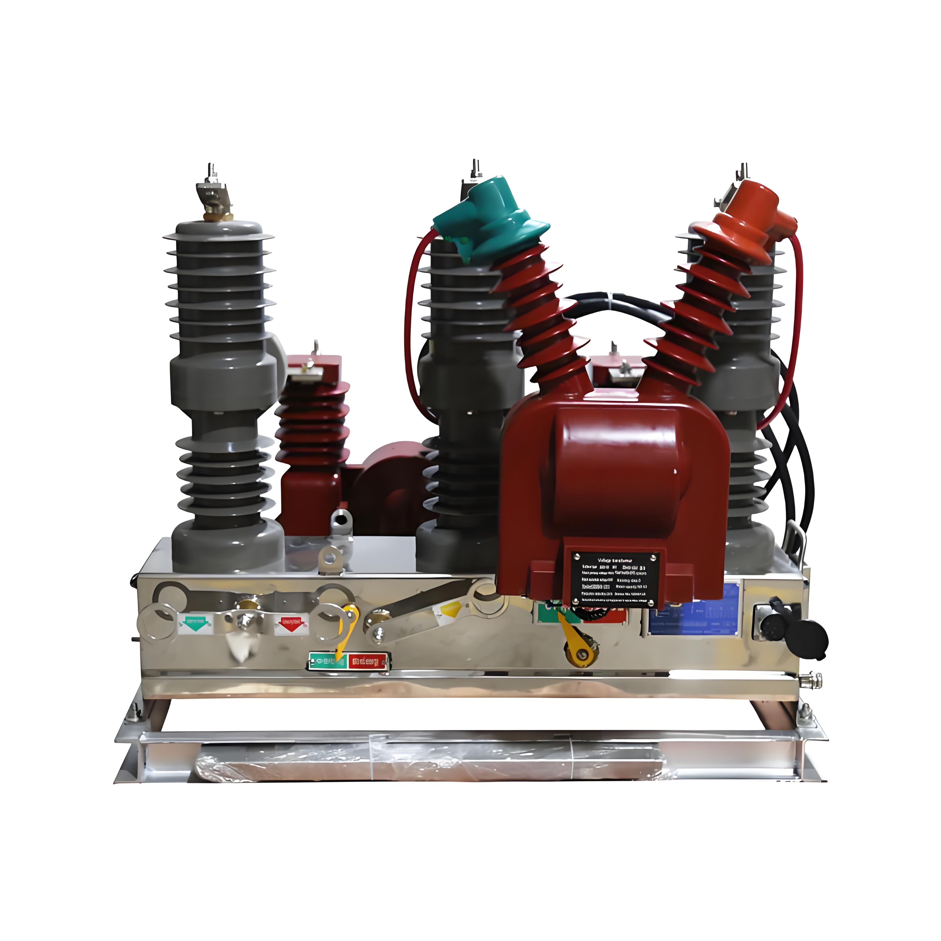
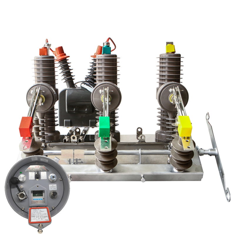
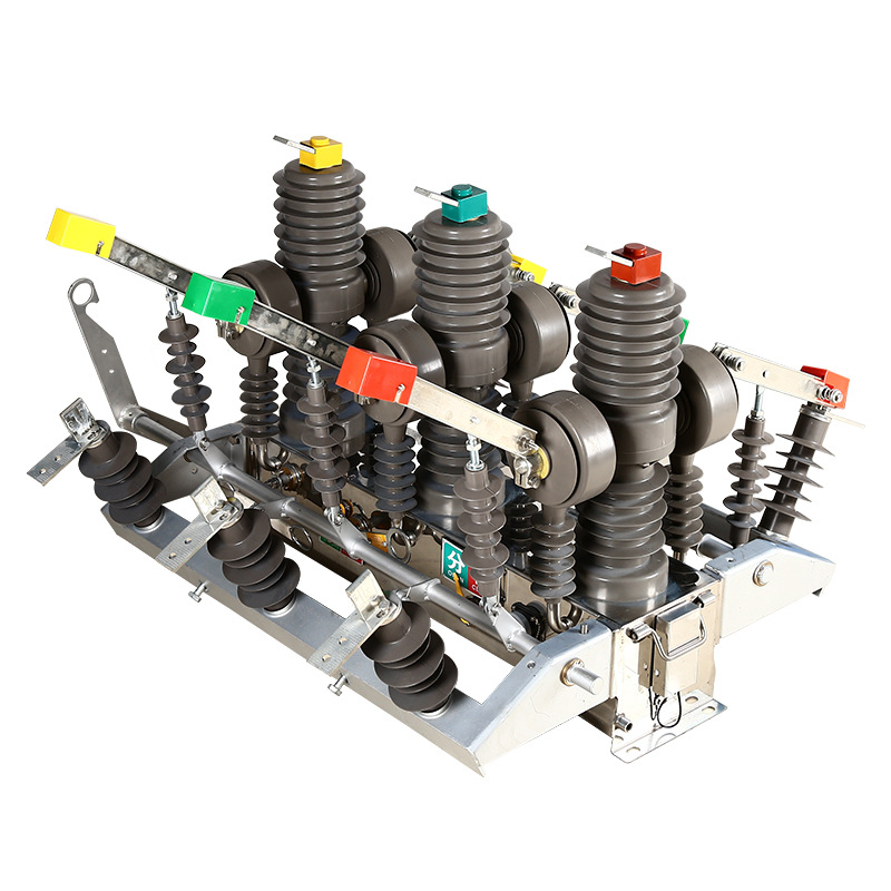
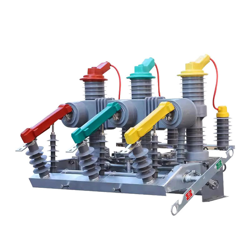
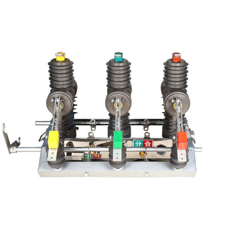
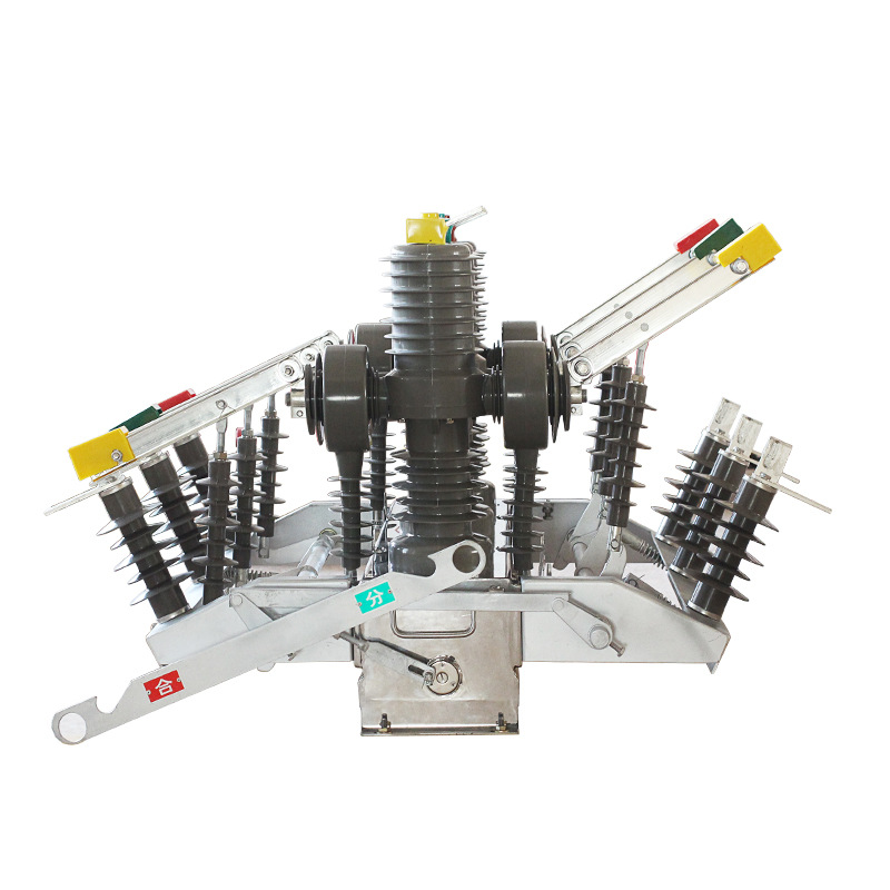
A double isolation dual-power vacuum circuit breaker is an integrated 10kV pole-mounted switching device that combines a vacuum interrupter, isolating switches on both sides, and an intelligent automatic transfer controller for two independent power sources.
In practical terms, one unit handles fault interruption, main/standby source transfer, and visible isolation for maintenance. This is why it is widely associated with ZW32-12GG and ZW10-12GG class equipment in overhead distribution networks.
Why Important 10kV Loads Need More Than a Standard Dual-Power Breaker
A normal dual-power switching device can transfer between two incoming feeders, but many versions do not provide a visible disconnection point on both sides. For medium-voltage maintenance crews, that is a major issue.
At 10kV, utilities and industrial owners often require a clear, visible open point before grounding and service work. A standard transfer-only breaker may switch power, but it does not always satisfy the real-world safety need for an electrical isolation safety mechanism that technicians can visually verify.
That gap is exactly why the double isolation vacuum circuit breaker exists. It is not just about keeping power on. It is about switching safely, isolating clearly, and preventing dangerous backfeed during maintenance.
What “Double Isolation,” “Dual Power,” and “Vacuum Circuit Breaker” Mean
The product name sounds technical, but each part describes a specific job inside the equipment. Understanding those three terms makes selection much easier.
What Is a Vacuum Circuit Breaker?
The vacuum circuit breaker is the core switching and protection element. Its vacuum interrupter is designed to interrupt load current, overload current, and short-circuit current with high reliability in 10kV systems.
What Does Double Isolation Mean?
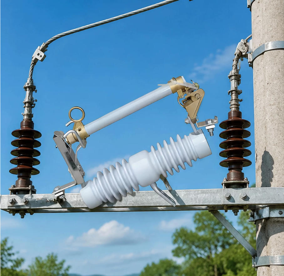
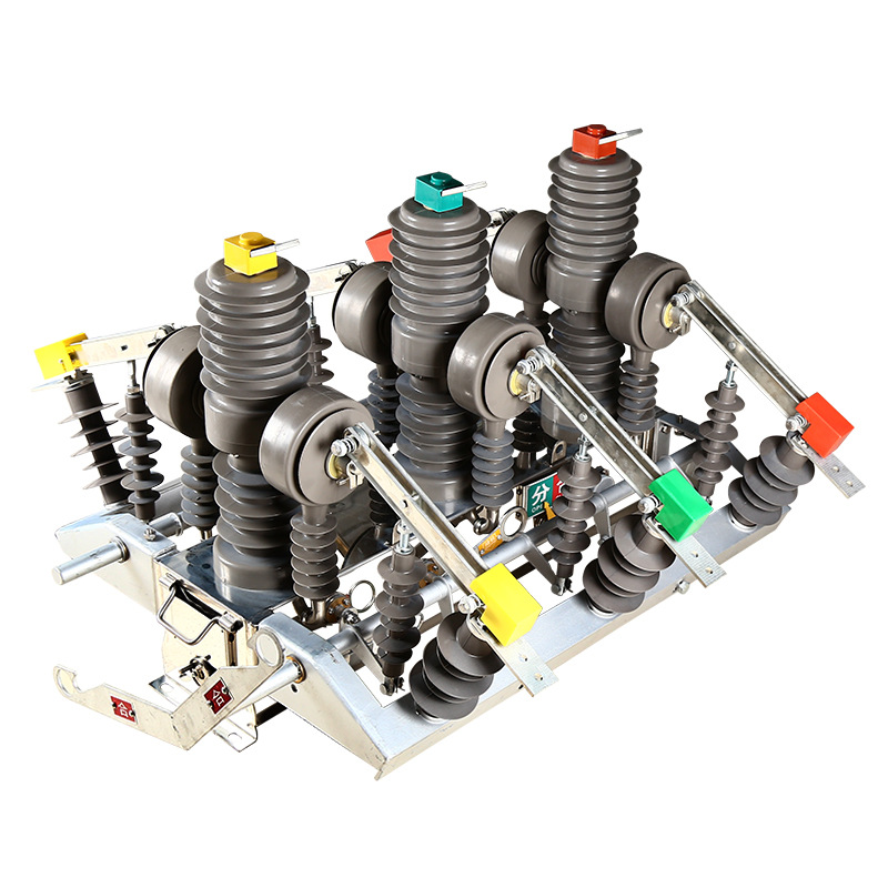
Double isolation means the unit includes isolating switches on both the source side and the load side, or on both A and B power paths depending on the scheme. This creates two independent visible disconnection points for safer maintenance and grounding procedures.
What Does Dual Power Mean?
Dual power means the device accepts two independent 10kV feeders, typically a main source and a standby source. The built-in controller performs automatic power source switching when the main source fails, while interlocks prevent parallel operation and reverse feed.
How a Double Isolation Dual-Power Vacuum Circuit Breaker Works
The operating sequence is straightforward but highly controlled. The controller continuously monitors voltage through PT inputs on the main and standby sources.
If the main source loses voltage or a transfer condition is met, the breaker opens according to programmed logic. After a set delay, and only if the standby source is healthy, the standby side is closed.
When the main source recovers, the controller can either automatically return to normal supply or remain on standby source if non-return mode is selected. Throughout the process, interlocks ensure the two sources are never paralleled.
Main Components Inside the Integrated Switch
This device replaces a more complicated arrangement by integrating all the major modules into one outdoor unit.
Vacuum Interrupter Assembly
This is the core fault-clearing section. It performs normal switching and interrupts fault current during overload, short-circuit, and protection trip events.
A and B Incoming Isolation Switches
These two isolator sets create visible breaks on both power paths. During maintenance, crews can clearly confirm disconnection rather than relying only on control indications.
Operating Mechanism
Spring-operated or permanent magnet mechanisms execute open and close actions. The choice affects maintenance style, response consistency, and mechanism life.
CTs and PTs
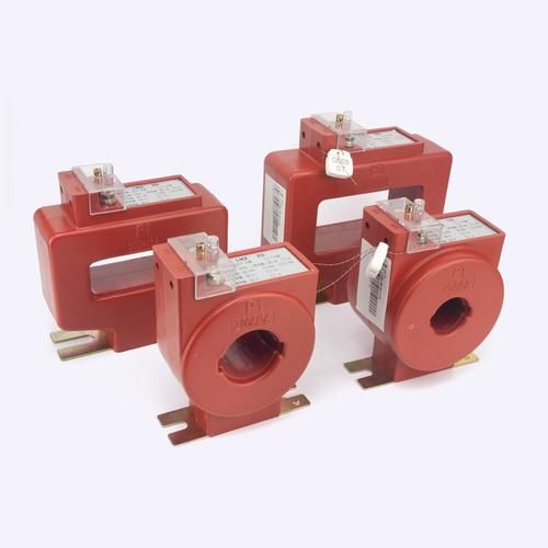
Current transformers and potential transformers provide the measurement foundation for protection and transfer logic. CTs support overcurrent and earth fault functions, while PTs support undervoltage detection and source health judgment.
Intelligent Automatic Transfer Controller
This controller manages voltage monitoring, transfer timing, no-parallel interlocking, fault lockout, and source selection logic. In modern projects, it may also support remote signaling, remote measurement, remote control, and remote adjustment.
Mechanical and Electrical Interlocks
These interlocks are essential. They prevent isolator operation unless the breaker is open, and they prevent the main and standby sources from being closed at the same time.
Key Features and Benefits for 10kV Pole-Mounted Distribution Systems
For utilities, industrial users, and EPC teams, the appeal is simple: one compact outdoor device delivers protection, transfer, and visible isolation in a single package.
One Device Replaces “Two Breakers Plus Two Isolators”
A traditional arrangement often uses two separate vacuum breakers plus multiple isolators and a transfer control scheme. A ZW32-12GG or ZW10-12GG class integrated unit can reduce pole-top hardware, simplify wiring, and cut installation time.
That matters on real overhead lines where mounting space, conductor routing, and maintenance access are all limited.
Dual Visible Isolation Points Improve Maintenance Safety
This is the biggest differentiator. Crews can open both sides and confirm a visible break before grounding and inspection, which directly improves maintenance confidence and supports high-voltage safety compliance.
Full Protection Functions for Medium-Voltage Networks
A well-configured unit supports medium-voltage switchgear protection functions such as overcurrent, instantaneous short-circuit trip, earth fault protection, PT disconnection blocking, and fault lockout. It is not just a transfer switch; it is a protection device.
Automatic Transfer and Optional Auto-Reclosing Logic
Typical logic includes loss-of-voltage tripping, transfer delay, standby closing, and optional automatic return to the preferred source. Some users choose non-return mode to avoid unnecessary reclosing after upstream instability.
Outdoor Automation Compatibility
These breakers are designed for outdoor pole-top use and can be equipped for feeder automation. In many projects, four-remote capability is required so dispatchers can monitor status, receive alarms, control switching, and read measurements remotely.
Double Isolation vs Standard Dual-Power Vacuum Circuit Breaker
The most important buying difference is simple: a standard dual-power vacuum breaker mainly performs transfer between two sources, while a double isolation dual-power vacuum breaker adds visible isolation on both sides for safer maintenance.
That difference affects operating procedures, utility acceptance, field safety, and total equipment count.
Comparison Table: Double Isolation Dual-Power Breaker vs Ordinary Dual-Power Breaker
| Item | Double Isolation Dual-Power Breaker | Ordinary Dual-Power Breaker |
|---|---|---|
| Visible isolation points | Yes, on both sides / both source paths | Usually no dual visible break |
| Maintenance safety | High, clear disconnection for grounding and inspection | Lower, often needs additional isolators |
| Interlocking | Breaker-isolator and source-to-source interlocking | Mainly source transfer interlocking |
| Equipment count | Integrated one-unit scheme | Often requires supplementary devices |
| Pole-top footprint | Smaller than traditional multi-device layout | Can be larger if external isolation is added |
| Typical applications | Critical 10kV outdoor loads needing ATS plus visible isolation | Basic dual-source switching where visible isolation is not the main requirement |
Typical Ratings and Configuration Table for 10kV Models
| Parameter | Typical Configuration |
|---|---|
| System voltage | 10kV class / 12kV rated equipment |
| Frequency | 50Hz or 60Hz |
| Installation type | Outdoor pole-mounted |
| Source arrangement | Two independent feeders, main + standby |
| Core switching element | Vacuum interrupter |
| Isolation arrangement | Double-side visible isolating switches |
| Controller functions | Voltage monitoring, automatic transfer, auto-return or non-return mode, interlocking |
| Protection items | Overcurrent, instantaneous trip, earth fault, PT failure blocking, fault lockout |
| Operating mechanism | Spring or permanent magnet |
| Communication options | Remote telemetry, telesignaling, telecontrol, telemetering |
Real-World Application Scenarios Where This Breaker Is Commonly Used
This equipment is most valuable where outage time is expensive and maintenance isolation must be obvious. That combination is common in 10kV overhead supply systems serving critical users.
Industrial Parks and Large Commercial Campuses
Large campuses often have two utility 10kV feeders in main/standby configuration. A dual-power transfer vacuum breaker with double isolation reduces pole structure complexity and makes source transfer faster after a feeder loss.
Hospitals, Data Centers, and Telecom Sites
These loads cannot tolerate long interruptions. Automatic standby switching keeps continuity high, while visible isolation supports utility-approved maintenance procedures before line work begins.
Water Plants, Wastewater Sites, and Pumping Stations
Municipal water and wastewater systems depend on continuous motor loads. Outdoor 10kV integrated switching helps maintain process continuity while simplifying inspection and isolation during field repairs.
Mines, Oilfields, and Remote Energy Sites
Remote operations value rugged, compact hardware with anti-backfeed logic. In mines and oilfields, outdoor equipment that combines protection, transfer, and isolation reduces site complexity and operating risk.
Solar, Wind, and Energy Storage 10kV Interconnection Points
At renewable energy interconnection points, reverse feed risk must be controlled carefully. Double isolation helps maintenance teams establish a visible break, while transfer logic supports network continuity where dual incoming arrangements are used.
Distribution Boundary Points and Government or Emergency Facilities
At user boundary points, sectionalizing locations, and public infrastructure sites, continuity and safety are equally important. This is where an automatic power source switching breaker with visible isolation provides clear operational value.
Real-World Data and Example Use Cases
Buyers often ask whether the integrated design produces measurable benefits. In field projects, it usually does.
The exact figures vary by utility standard and pole structure, but installers regularly report fewer mounted devices, fewer jumper connections, and faster restoration steps compared with older multi-device schemes.
Example: Industrial Park Main Incomer
A manufacturing park in East Asia used two independent 10kV utility feeders for a 6 MVA campus load. By using one ZW32-12GG-class integrated unit instead of a traditional arrangement, the contractor reduced visible pole-top primary devices from four major switching elements to one integrated breaker body with built-in double isolation, cutting installation complexity significantly.
During a feeder undervoltage event, standby transfer was completed after the programmed delay, restoring the main high-voltage supply path in well under a minute. For the owner, that meant avoiding a full park-wide manual transfer process.
Example: Hospital 10kV Standby Source Switching
A regional hospital with dual 10kV incoming lines required automatic transfer for critical medical infrastructure. The controller was set for undervoltage detection on the preferred feeder, delayed transfer to the standby feeder, and automatic return only after normal voltage stability was confirmed.
The crucial point was not only transfer speed. Utility maintenance staff also required visible isolation before upstream work, which a standard transfer-only breaker could not provide without extra isolators.
Example: Water Pumping Station Outdoor Installation
A municipal pumping station feeding more than 80,000 residents used an outdoor pole-mounted arrangement where space was tight and maintenance access was limited. Replacing a “two breakers plus isolators” layout with an integrated unit reduced hardware count and simplified the operating sequence for field personnel.
In practical terms, crews had fewer primary connections to inspect and a clearer isolation state during scheduled maintenance windows.
Example Data Table: Traditional Scheme vs Integrated Double Isolation Scheme
| Comparison Item | Traditional Two-Breaker + Isolator Scheme | Integrated Double Isolation Scheme |
|---|---|---|
| Primary device count | Higher | Lower |
| Structure complexity | More brackets, links, jumpers, and coordination points | More compact integrated structure |
| Pole-space usage | Larger | Smaller |
| Maintenance clarity | Can depend on multiple external devices | Clear visible isolation within one coordinated unit |
| Installation cost direction | Often higher in total assembled hardware and labor | Often more economical overall |
| Transfer and protection integration | May require extra control coordination | Built into one controller architecture |
Protection and Interlocking Logic Explained
This equipment is both a protection device and a transfer device. That combination is what makes it especially useful in critical 10kV networks.
Fault Protection Logic
When overcurrent, short-circuit, or ground fault conditions are detected through CT inputs, the breaker opens to isolate the fault. The vacuum interrupter performs the actual interruption duty.
Transfer Blocking Logic
Transfer must not occur blindly. Fault lockout and PT failure blocking are used so the controller does not close onto an unhealthy source or make a wrong transfer decision due to missing voltage signals.
No-Parallel Interlocking Logic
The controller and interlocks ensure the two feeders cannot be closed simultaneously. This is critical because these systems are designed for main/standby transfer, not continuous parallel operation.
Isolator Operation Interlock
The isolating switches cannot be operated under load because the breaker must be open first. This mechanical and electrical interlock prevents dangerous attempts to open an isolator while current is still flowing.
When to Choose This Device and When Not to
This solution is highly effective, but not universal. The application has to match the design intent.
Best-Fit Conditions
Outdoor pole-mounted 10kV distribution applications
Two independent feeders in main/standby arrangement
Important loads that require automatic transfer
Projects where visible isolation is required for safe maintenance
Utility or industrial sites needing combined protection and transfer logic
Poor-Fit Conditions
Indoor switchgear lineups where a cabinet-type solution is more appropriate
Systems that require long-term parallel operation of two sources
Low-priority single-feed loads with no real transfer requirement
Projects where visible outdoor isolation is not part of the safety procedure
How to Select the Right Double Isolation Vacuum Circuit Breaker
Selection should start with the actual network and operating procedure, not just a model number. Good specifications prevent field problems later.
Confirm Voltage Class and Fault Level
Rated voltage, insulation level, and short-circuit breaking capacity must match the network. For most overhead applications, buyers are really selecting a 12kV-rated device for 10kV system use.
Confirm Main-Standby Logic Requirements
Define the transfer delay, undervoltage criteria, return conditions, and whether auto-return or non-return mode is preferred. This logic should match the utility operating philosophy.
Confirm Protection and Instrument Transformer Needs
CT and PT quantity, ratio, and accuracy affect transfer reliability and protection coordination. If earth fault sensitivity is important, that should be addressed early in the specification.
Confirm Communication and Automation Requirements
Feeder automation and SCADA projects may require four-remote functions and protocol compatibility. If remote dispatch is part of the plan, communication details cannot be left until the last minute.
Confirm Safety and Mechanical Interlock Requirements
Verify visible break requirements, grounding procedure compatibility, and anti-misoperation design. On many projects, these details determine whether the equipment is accepted by the owner and utility.
Featured Snippet Summary: What Makes Double Isolation Dual-Power Breakers Different?
A double isolation dual-power vacuum circuit breaker is different because it combines two visible isolation points, automatic transfer between two independent 10kV sources, and medium-voltage fault protection in one integrated outdoor pole-mounted unit. The defining advantage is not only transfer capability, but safe, visible isolation for maintenance.
FAQ
What is the difference between a double isolation dual-power vacuum circuit breaker and a normal dual-power breaker?
The double isolation type adds isolating switches on both sides or both source paths, creating visible disconnection points for safer maintenance. A normal dual-power breaker usually focuses on source switching only and may not provide dual visible isolation.
Can a double isolation dual-power vacuum circuit breaker run two 10kV sources in parallel?
No. Built-in mechanical and electrical interlocks are designed to prevent parallel operation and reverse power feed between the two incoming sources.
Is this breaker mainly used at 10kV?
Yes. It is most commonly used in 10kV outdoor pole-mounted distribution systems, especially in ZW32-12GG and ZW10-12GG class applications.
What protection functions are usually included?
Typical functions include overcurrent protection, instantaneous short-circuit trip, earth fault protection, PT failure blocking, and transfer lockout logic.
Why is visible isolation important in medium-voltage maintenance?
Visible isolation gives crews a clear disconnection point for grounding, inspection, and safer compliance with high-voltage maintenance procedures. It reduces ambiguity during field work.
Is this suitable for indoor switchgear panels?
Generally no. This product is mainly intended for outdoor pole-mounted applications rather than indoor switchgear lineups.
Which industries use dual-power transfer vacuum breakers with double isolation most often?
Common users include hospitals, data centers, industrial parks, mines, oilfields, water utilities, pumping stations, telecom sites, and renewable energy facilities.
How does automatic power source switching work after a main feeder failure?
The controller detects voltage loss or a qualifying fault condition, trips the breaker as required by logic, applies a transfer delay, and closes the standby source if its voltage is healthy and interlock conditions are satisfied.
Conclusion
The double isolation dual-power vacuum circuit breaker is a practical answer for critical 10kV outdoor systems that need more than basic transfer switching. It combines vacuum interruption, electrical isolation safety mechanism design, and automatic source transfer into one compact piece of medium voltage switchgear protection equipment.
For buyers comparing options, the key question is simple: do you only need source switching, or do you also need visible, two-side isolation for compliant maintenance? If the answer is both, this integrated design is usually the stronger engineering choice.
Manufacturers such as Weisho Electric typically position this type of equipment for pole-mounted main/standby 10kV applications where reliability, anti-backfeed interlocking, and maintenance safety all matter at the same time.
CTA
Need help selecting the right ZW32-12GG or ZW10-12GG class breaker for your project?
Send your 10kV single-line diagram, source arrangement, protection requirements, and automation needs for a fast technical review. Compare specifications, confirm transfer logic, and get model selection guidance for the right double-isolation vacuum circuit breaker before procurement.
Contact us now to request a quotation, application matching, or engineering support for your dual-power transfer vacuum breaker project.