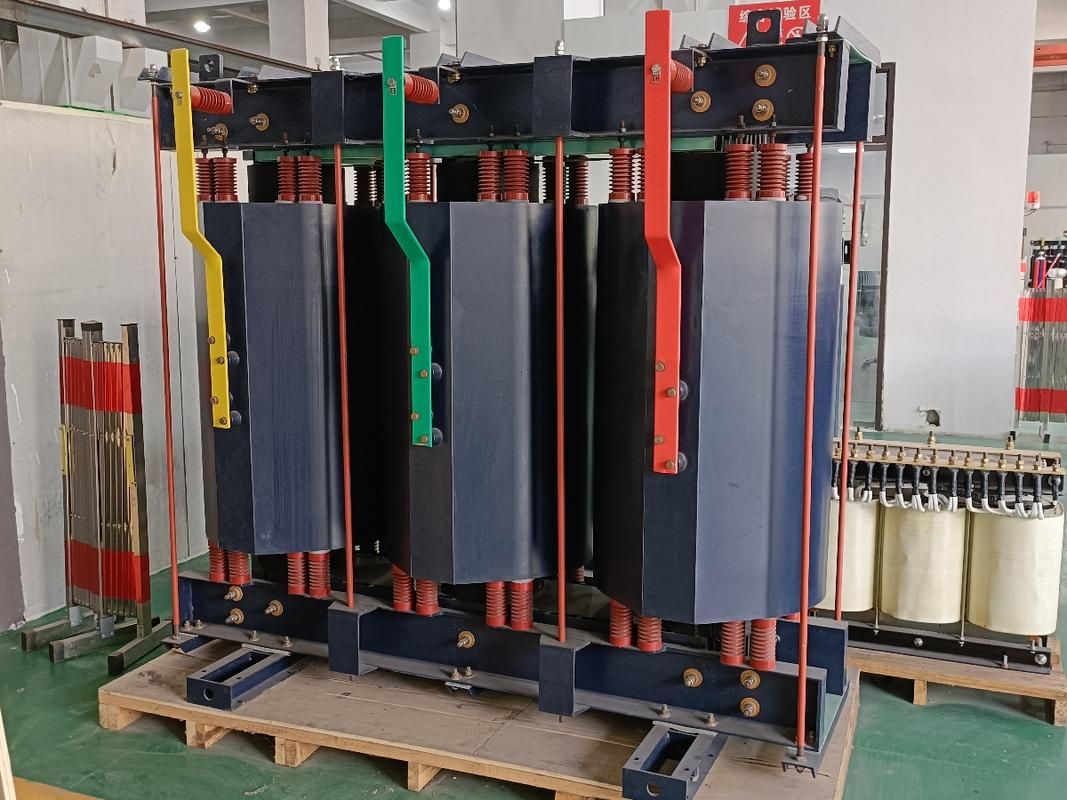
In a reactive power compensation system, a reactor is an inductive component used to control current, suppress harmonics, prevent resonance, and support stable voltage conditions. Its value is not limited to adding inductance: the correct reactor changes how a capacitor bank interacts with the electrical network during switching, normal operation, and abnormal harmonic conditions.
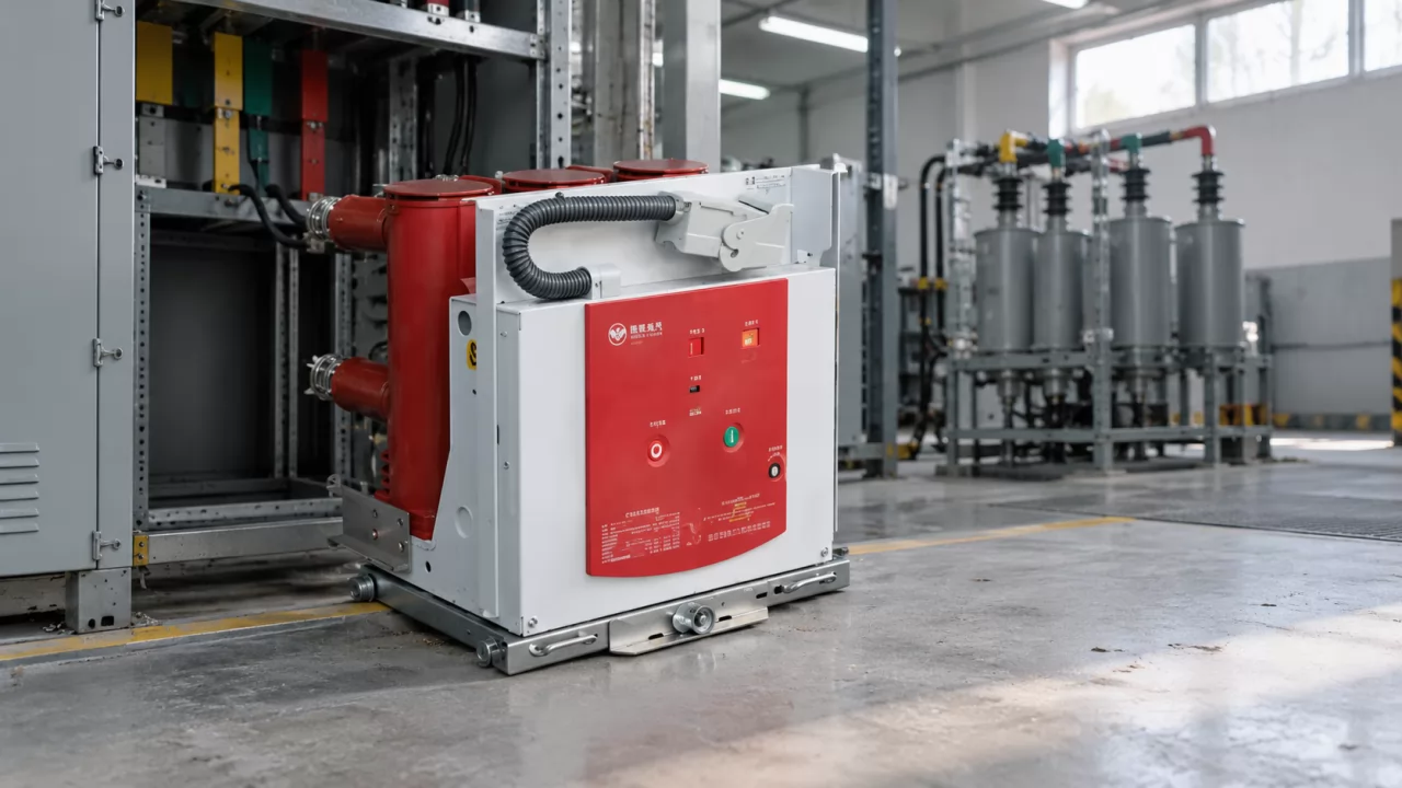
The most common reactor installed inside a low-voltage or medium-voltage capacitor compensation cabinet is a series reactor. It is connected in series with the compensation capacitor and is designed to protect the capacitor bank, switching equipment, and upstream electrical system.
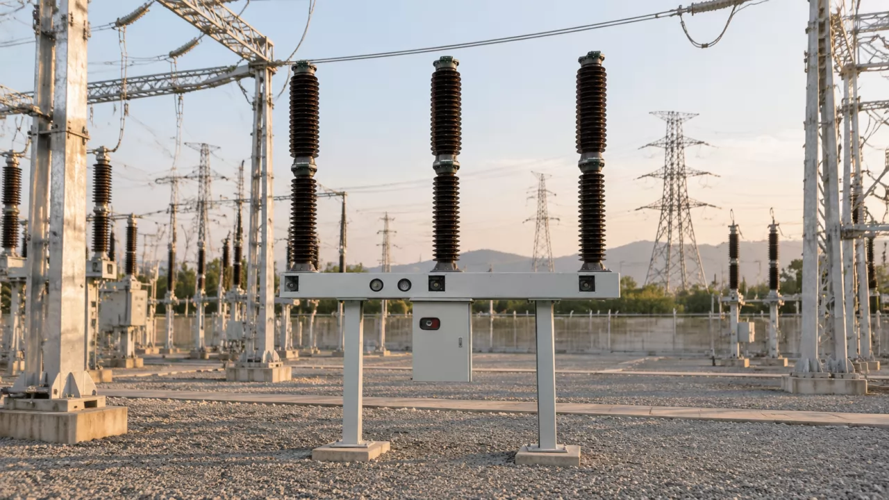
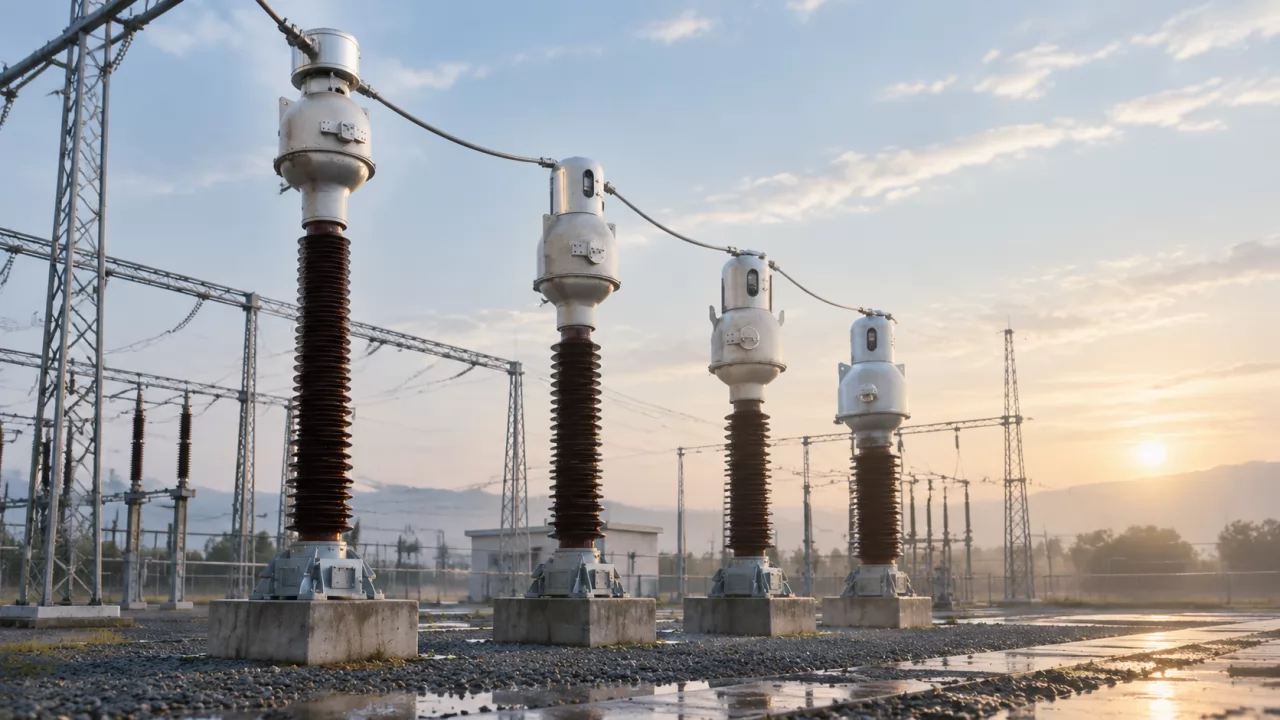
A different device, called a shunt reactor, is generally connected in parallel with a high-voltage bus or transmission line. It absorbs excess capacitive reactive power and is mainly used on long overhead lines, lightly loaded networks, and high-voltage systems where voltage rise is a concern.
Understanding this distinction is essential. A series reactor is normally used with capacitor compensation equipment, while a shunt reactor is used for inductive reactive power compensation and voltage control on high-voltage networks.
What Is a Reactor in a Reactive Power Compensation System?
A reactor is an electrical device with inductive reactance. When alternating current flows through its winding, the reactor resists changes in current and creates a voltage drop that depends on the current, frequency, and inductance.
In practical power systems, this behavior gives the reactor several important functions:
Current control: It limits rapid changes in current and reduces transient current peaks.
Harmonic control: It changes the impedance of the circuit at different frequencies.
Resonance control: It shifts the natural resonance point of the network.
Voltage control: A shunt reactor absorbs capacitive reactive power, while a series reactor affects voltage distribution within a capacitor branch.
Equipment protection: It reduces electrical stress on capacitors, contactors, circuit breakers, and busbars.
In a capacitor compensation cabinet, the reactor and capacitor work as one engineered branch. The capacitor supplies capacitive reactive power to improve power factor, while the reactor controls the capacitor branch so that compensation does not create excessive switching current or harmonic amplification.
This is why the reactor function in power systems should be evaluated together with the capacitor bank, nonlinear loads, transformer impedance, short-circuit level, and switching method. Selecting a reactor by current rating alone is not sufficient.
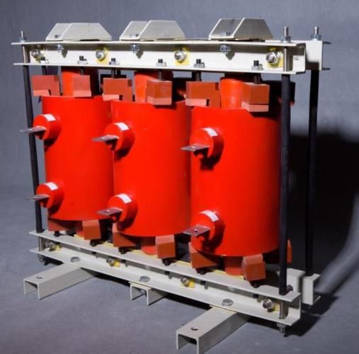
Why Is a Reactor Needed in a Capacitor Compensation Cabinet?
Capacitors improve power factor by supplying capacitive reactive power to offset inductive loads such as motors, transformers, welding machines, and magnetic ballasts. However, a capacitor bank also changes the impedance of the electrical system and may create unwanted electrical stress if it is connected without suitable reactor protection.
Four problems are particularly important: capacitor switching inrush, harmonic amplification, parallel resonance, and increased capacitor terminal voltage.
| Problem Without a Reactor | Possible Consequence | Reactor-Based Protection |
|---|---|---|
| Capacitor switching inrush | Damage to capacitors, contactors, fuses, or switching devices | Limits transient current by adding inductive impedance |
| Harmonic current amplification | Capacitor overheating, bulging, premature aging, or failure | Forms a detuned or tuned filtering branch |
| Parallel resonance | Harmonic overvoltage, unstable current, nuisance tripping, or equipment damage | Shifts the resonance point away from harmful frequencies |
| Increased capacitor terminal voltage | Capacitor dielectric stress and reduced service life | Requires an appropriate capacitor voltage rating and system design |
Capacitor Switching Inrush
When a capacitor stage is energized, the voltage difference between the capacitor and the busbar can produce a very large transient current. The peak is influenced by the remaining capacitor voltage, transformer impedance, cable impedance, the number of already energized stages, and the exact switching instant.
Without adequate impedance, this current can damage capacitor terminals, weld contactor contacts, blow fuses, or cause severe electromagnetic stress in the cabinet. The reactor limits the rate at which current rises and reduces the peak stress seen by the switching circuit.
Harmonic Amplification
Modern industrial facilities commonly use variable-frequency drives, six-pulse rectifiers, UPS systems, battery chargers, welding equipment, and switched-mode power supplies. These nonlinear loads draw current that is not a clean sine wave.
Capacitors offer low impedance to higher-frequency components. As a result, a capacitor bank can attract harmonic current from the network. If the system impedance and capacitor impedance interact at an unfavorable frequency, the harmonic current may be amplified instead of reduced.
The consequences can include capacitor overheating, dielectric deterioration, internal pressure rise, bulging cases, blown capacitor fuses, and repeated stage failures. A series reactor reduces this risk by changing the frequency-dependent impedance of the capacitor branch.
Parallel Resonance
Parallel resonance occurs when the inductive impedance of the upstream network and the capacitive impedance of the compensation bank interact at a particular frequency. Near that frequency, even a modest harmonic current can create a disproportionately high voltage.
This condition is especially dangerous when the resonance frequency is close to the fifth or seventh harmonic, because these are common harmonic components in industrial power systems. A reactor helps move the resonance point away from dominant harmonic frequencies.
Increased Capacitor Terminal Voltage
A series reactor and capacitor share the branch voltage according to their reactances. Under normal operating conditions, the voltage across the capacitor can be slightly higher than the busbar voltage because of the voltage-boosting effect created by the series reactor.
For this reason, a capacitor selected only for the nominal busbar voltage may be under-rated. The capacitor voltage rating must be checked against the actual branch voltage, reactor percentage, harmonic current, and operating temperature.
What Is the Main Function of a Series Reactor?

A series reactor is connected in series with the compensation capacitor. Its primary role is to protect and condition the capacitor branch while allowing the capacitor to provide reactive power correction.
In practical installations, its main functions are:
Limiting capacitor energization inrush current.
Reducing the risk of fifth- and seventh-harmonic amplification.
Shifting the system resonance point.
Reducing harmonic current entering the capacitor bank.
Improving the operating reliability of contactors and switching devices.
Supporting longer capacitor service life.
Creating a predictable impedance for a detuned or tuned filter branch.
A series reactor does not replace the capacitor. It also does not normally provide the primary power-factor correction. The capacitor supplies the leading reactive current, while the reactor controls how that current interacts with the electrical network.
How Does a Series Reactor Suppress Capacitor Inrush Current?
During capacitor energization, the reactor adds inductive reactance to the branch. This increases the effective impedance seen by the transient current and slows the current rise, reducing the instantaneous peak.
The reactor cannot remove the transient completely, because the capacitor must still be energized. Its purpose is to make the transient lower, slower, and more manageable for the capacitor, contactor, fuse, and upstream switchgear.
For example, consider a 400 V industrial capacitor bank that switches several stages during a production shift. If one stage is energized while another stage is already connected, the voltage difference and low system impedance may create a severe current pulse. A suitable series reactor reduces the pulse and helps prevent repeated contactor welding or capacitor fuse operation.
Reactor protection should be considered together with switching technology. Capacitor-duty contactors, pre-insertion resistors, synchronous switching, discharge resistors, and properly coordinated fuses may all be required depending on the bank size and system voltage.
How Does a Series Reactor Reduce Harmonics?
The reactor and capacitor form a frequency-selective branch. By selecting the reactor inductance and capacitor value correctly, the designer can establish a detuned or tuned response that reduces the likelihood of harmonic amplification.
The most common harmonic concerns in industrial networks are the fifth and seventh harmonics. They are often associated with six-pulse rectifiers and variable-frequency drives, although the actual harmonic spectrum must be measured rather than assumed.
A series reactor for harmonic reduction does not automatically remove every harmonic. It is designed to address specific frequency behavior and must be coordinated with the measured harmonic current, system impedance, capacitor rating, and desired compensation capacity.
For example, a factory with a high concentration of motor drives may experience significant fifth-harmonic current. A 6% reactor is commonly used to reduce the risk of fifth-harmonic amplification in such a capacitor compensation system.
It is important to distinguish between detuned compensation and a fully tuned passive filter. A detuned branch is generally designed to avoid resonance with dominant harmonics. A tuned filter is designed to provide a low-impedance path for a selected harmonic and requires more detailed engineering, protection, and performance verification.
How Does a Series Reactor Prevent Parallel Resonance?
The reactor changes the total inductive and capacitive reactance of the branch. This shifts the effective resonance frequency so that it is less likely to coincide with a strong harmonic generated by the facility.
The exact resonance point depends on more than the reactor percentage. Transformer impedance, cable length, short-circuit capacity, capacitor kvar, other capacitor stages, and the harmonic-producing loads all affect the result.
A system with a weak transformer and a relatively large capacitor bank can be more sensitive to resonance than a system connected to a strong utility source. The same capacitor bank may therefore behave differently in two plants with identical nominal voltage and load capacity.
Engineers should review both the existing and planned compensation stages. Switching additional stages changes the total capacitance and can move the resonance frequency. Automatic compensation controllers should also be configured to avoid unnecessary stage switching under lightly loaded conditions.
How Does a Series Reactor Affect Capacitor Voltage?
In a series reactor-capacitor branch, the reactor produces a voltage drop that changes the voltage distribution across the branch. Under the operating condition of interest, the capacitor terminal voltage may be higher than the system busbar voltage.
This is sometimes described as a voltage-boosting effect. It is a normal design consequence, not automatically a fault, but it must be included in the capacitor selection.
For example, a capacitor bank connected to a nominal 400 V bus may require capacitors rated above 400 V when a series reactor is installed. The correct rating depends on the reactor percentage, capacitor kvar, harmonic current, tolerance, and expected operating voltage.
Using a higher-rated capacitor may reduce the effective kvar output at the nominal bus voltage, so the compensation capacity should be recalculated. A design that checks voltage but ignores kvar performance can produce an undersized or inefficient compensation bank.
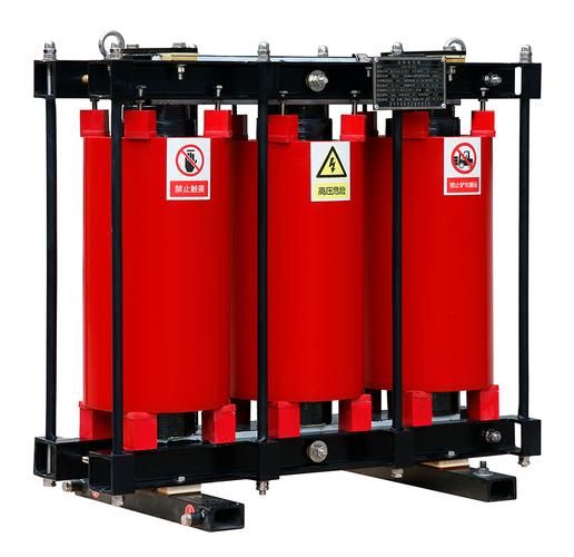
What Is the Difference Between a Series Reactor and a Shunt Reactor?
The terms “series reactor” and “shunt reactor” describe different connection methods and different engineering purposes. Confusing them can lead to an incorrect design, especially when discussing inductive reactive power compensation.
| Reactor Type | Connection | Primary Function | Typical Application |
|---|---|---|---|
| Series reactor | Connected in series with capacitors | Inrush-current limitation, harmonic reduction, and resonance detuning | Low- and medium-voltage capacitor compensation cabinets |
| Shunt reactor | Connected in parallel with the power system | Absorbs capacitive reactive power and controls voltage rise | Long overhead lines, lightly loaded transmission lines, and high-voltage buses |
Series Reactor in a Capacitor Compensation Cabinet
The series reactor is normally installed upstream or downstream of the capacitor unit according to the equipment design and insulation requirements. It carries the capacitor branch current and must be rated for continuous current, transient duty, harmonic heating, insulation level, and thermal conditions.
Its main purpose is protective and conditioning-oriented. It makes capacitor-based reactive power compensation safer and more stable in a network containing switching events and nonlinear loads.
Shunt Reactor on a High-Voltage Network
A shunt reactor is connected in parallel with the power system and absorbs capacitive reactive power. This is useful when a long overhead line or cable is lightly loaded, because the line capacitance can produce excess reactive power and cause the receiving-end voltage to rise.
For instance, a long transmission line may operate at a high voltage during a light-load period even though the connected demand is low. A shunt reactor draws inductive current and helps offset the line’s capacitive behavior.
A shunt reactor is therefore central to voltage regulation using reactors on high-voltage systems. It is not normally the reactor installed inside a low-voltage capacitor compensation cabinet.
How Does a Series Reactor Work in Reactive Power Compensation?
The capacitor supplies leading reactive current, while the reactor introduces inductive reactance in series with that capacitor. The combined branch has a controlled impedance that changes with frequency.
At the fundamental frequency, the branch is designed to provide the required compensation capacity without excessive current. At harmonic frequencies, the reactor increases the branch impedance and changes the current path, reducing the possibility that the capacitor will absorb damaging harmonic current.
The simplified inductive reactance relationship is:
XL = 2πfL
where XL is inductive reactance, f is frequency, and L is inductance. Because reactance increases with frequency, the reactor has a stronger impedance effect on harmonics than on the fundamental frequency.
The actual design also involves capacitor reactance, transformer impedance, upstream short-circuit impedance, cable impedance, and the harmonic spectrum. A reliable design must therefore use system data rather than a generic rule alone.
Series Reactor for Harmonic Reduction
Reactor percentage is commonly used to describe the relationship between the reactor reactance and the capacitor reactance at the fundamental frequency. Typical values include 6% and 14%, but other values may be required for special filtering or detuning objectives.
| Typical Reactor Percentage | Common Design Purpose | Practical Consideration |
|---|---|---|
| 6% | Commonly used to suppress fifth-harmonic amplification | Suitable where fifth-harmonic risk is significant, subject to system verification |
| 14% | Commonly associated with third-harmonic suppression applications | Requires careful evaluation of capacitor voltage, current, and resonance behavior |
| Other values | Customized harmonic filtering or detuning | Must be calculated from network impedance and the measured harmonic spectrum |
The relationship between a percentage value and harmonic behavior should not be treated as universal. A 6% reactor is commonly selected for fifth-harmonic risk, while a 14% reactor is commonly associated with third-harmonic applications, but the final choice must be confirmed by calculation or measurement.
Third-harmonic conditions may be especially relevant in systems with single-phase nonlinear loads, three-phase four-wire distribution, magnetic equipment, and zero-sequence current paths. The neutral arrangement and transformer connection can affect whether third-harmonic current is contained, circulated, or transferred into the compensation branch.
What Are the Real-World Benefits of Using a Reactor?
The benefits of a reactor are most visible in facilities where capacitor stages fail repeatedly, contactors become damaged, or power-quality measurements show harmonic distortion near a compensation bank.
Typical applications include manufacturing plants, commercial buildings with large HVAC systems, data centers, water-treatment facilities, metal-processing sites, and distribution networks with extensive variable-speed drive usage.
Example: Industrial Capacitor Bank With Fifth Harmonics
Consider a manufacturing plant with several hundred kilowatts of variable-frequency drive load. Measurements at the main low-voltage switchboard show a dominant fifth-harmonic current and repeated overheating in the capacitor cabinet.
Without a reactor, the capacitor bank may present a low-impedance path for the fifth harmonic. The resulting current increases the capacitor RMS current and internal losses, even when the fundamental-frequency kvar appears normal.
A common engineering response is to install a 6% series reactor with each capacitor stage or with a properly designed bank. The reactor shifts the resonance behavior and reduces the risk of fifth-harmonic amplification.
After installation, the engineer should verify capacitor current, reactor temperature, bus voltage, total harmonic distortion, fifth-harmonic current, and power factor under different load conditions. The result should be confirmed during both peak production and low-load operation, because the electrical behavior can change significantly.
Example: High-Voltage Line With Light Load
Suppose a long overhead transmission line supplies a remote area during a period when the demand is low. The line capacitance produces capacitive reactive power, and the receiving-end voltage rises above the desired operating level.
A shunt reactor connected to the high-voltage bus absorbs part of this capacitive reactive power. This supports voltage regulation and reduces the likelihood of excessive voltage stress on transformers, insulators, and connected equipment.
This application is different from protecting a capacitor bank. The shunt reactor is intentionally consuming inductive reactive power, while the capacitor bank is normally intended to supply capacitive reactive power for power-factor correction.
Example: Capacitor Switching in a Motor Control System
Consider a motor control system in which an automatic controller switches capacitor stages as motor load changes. When a stage is connected, the capacitor may be exposed to a high instantaneous current caused by the voltage difference between the energized bus and the capacitor.
A series reactor limits the current peak and reduces mechanical and thermal stress on the contactor. It also reduces the possibility that repeated switching will accelerate capacitor aging.
In a properly engineered system, the reactor is coordinated with capacitor-duty contactors, discharge resistors, fuses, controller delay settings, and the minimum time between stage switching operations. This coordination is important because a reactor cannot compensate for an incorrectly configured controller or an unsuitable switching device.
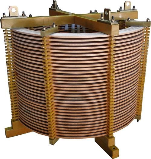
How Should Engineers Select a Reactor for Reactive Power Compensation?
Reactor selection should begin with the electrical system rather than the product catalog. Engineers should collect operating data and identify whether the objective is inrush limitation, harmonic detuning, tuned filtering, voltage control, or a combination of these functions.
| Selection Parameter | Why It Matters |
|---|---|
| System and capacitor voltage | The reactor can increase capacitor terminal voltage, so insulation and capacitor ratings must be suitable |
| Compensation capacity in kvar | Determines branch current and the required reactor continuous-current rating |
| Harmonic order and amplitude | Identifies whether the design requires detuning, filtering, or broader harmonic mitigation |
| Reactor percentage | Sets branch impedance and influences resonance behavior |
| Short-circuit level | Influences transient current, fault duty, and equipment withstand requirements |
| Ambient temperature and cooling | Determines continuous thermal performance and allowable temperature rise |
| Switching frequency | Affects inrush stress, contactor wear, and transient heating |
| Installation altitude and enclosure | May affect insulation clearance, ventilation, and thermal dissipation |
| System grounding and neutral arrangement | Can influence third-harmonic circulation and protection behavior |
Confirm the System Voltage and Capacitor Voltage
The nominal bus voltage is only the starting point. The design should calculate the expected voltage across the capacitor after the series reactor is installed, including normal voltage variation and harmonic effects.
Using a capacitor with an insufficient voltage rating can cause accelerated dielectric aging, increased internal pressure, and premature failure. The selected voltage rating should also reflect the actual capacitor manufacturer’s operating limits.
Calculate the Compensation Current
The reactor must carry the capacitor branch current continuously. Harmonic current can increase the RMS current above the value calculated from fundamental-frequency kvar alone.
Thermal design should therefore include the expected harmonic spectrum, not just the nominal 50 Hz or 60 Hz current. The reactor’s winding, insulation, terminals, and enclosure ventilation must all be suitable for the actual duty.
Measure Harmonics Before Choosing the Percentage
A power-quality analyzer can identify total harmonic distortion and individual harmonic orders at the main bus and near the proposed capacitor installation point. Measurements should cover different production states because a plant may have very different harmonic behavior during full load, partial load, and idle periods.
A single measurement taken during a quiet operating period may miss the condition that causes capacitor failures. Data logging over several days is often more useful than a brief spot check.
Evaluate Switching Conditions
The number of capacitor stages, stage size, switching sequence, minimum delay, residual capacitor voltage, and switching technology all affect inrush current. Larger stages generally produce more severe transients.
Automatic power-factor controllers should be configured to avoid rapid hunting between stages. If load changes quickly, a controller may repeatedly connect and disconnect capacitors, increasing both switching stress and mechanical wear.
Check Thermal and Mechanical Requirements
Reactors produce heat because their windings have resistance and because harmonic currents increase losses. The cabinet must provide adequate airflow, clearance, and separation from temperature-sensitive components.
Mechanical construction is also important. Reactor windings can experience electromagnetic forces during short circuits and switching events. Mounting, vibration control, terminal connections, and insulation support should be appropriate for the expected fault level.
What Happens If the Reactor Is Incorrectly Selected?
An incorrectly selected reactor may fail to protect the capacitor bank or may introduce new operating problems. The most common issue is choosing a percentage without evaluating the actual network impedance and harmonic spectrum.
Excessive capacitor voltage: The capacitor may operate above its intended voltage limit.
Insufficient harmonic suppression: Harmonic amplification may continue despite the reactor installation.
Reactor overheating: Harmonic current and inadequate cooling can produce excessive temperature rise.
Unwanted resonance: The selected branch may still resonate near a dominant harmonic frequency.
Reduced compensation performance: The capacitor may not deliver the expected kvar at the bus voltage.
Frequent protection operation: Fuses, breakers, or thermal protection may trip repeatedly.
Mechanical noise and vibration: Poor construction or loose mounting can create audible hum and long-term mechanical stress.
Another common mistake is installing a reactor with adequate fundamental current capacity but insufficient harmonic-current capability. A reactor can appear acceptable during commissioning and then overheat when nonlinear production equipment is operating at full output.
Protection coordination must also be reviewed. Capacitor fuses, reactor thermal protection, circuit breakers, contactors, and the automatic controller should operate together. An isolated component upgrade may not solve a system-level problem.
How Does a Reactor Support Inductive Reactive Power Compensation?
Inductive reactive power compensation is primarily associated with a shunt reactor. A shunt reactor absorbs excess capacitive reactive power from lines, cables, or lightly loaded high-voltage networks.
This is useful because long lines and underground cables have distributed capacitance. When the load is low, the capacitive current can cause voltage rise, sometimes known as the Ferranti effect in long transmission lines.
The shunt reactor draws inductive current and offsets part of that capacitive current. The result can be improved voltage control, reduced overvoltage risk, and more stable reactive power flow.
A series reactor has a different role. It does not normally provide the main inductive reactive power absorption for voltage regulation. Instead, it protects a capacitor-based compensation branch and controls the electrical interaction between the capacitors and the network.
Therefore, the phrase shunt reactor for reactive power compensation generally refers to high-voltage inductive compensation, while a series reactor is associated with capacitor-bank protection, harmonic reduction, and resonance detuning.
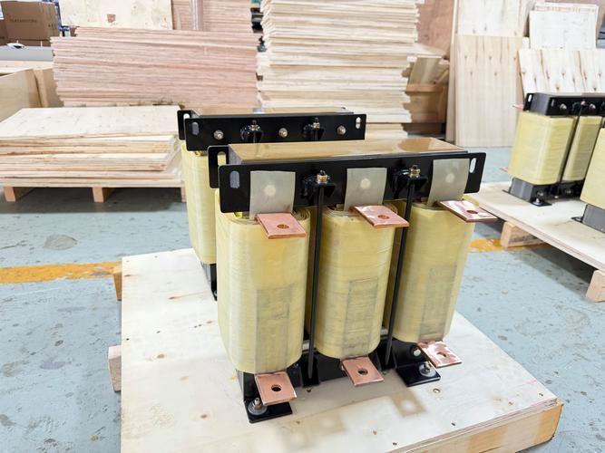
Reactor Function in Power Systems: Key Takeaways
A series reactor limits capacitor switching inrush current.
It helps reduce or filter harmful harmonic components, especially when the system is at risk from fifth- or seventh-harmonic amplification.
It shifts resonance points to reduce harmonic amplification and overvoltage.
It can raise capacitor terminal voltage, requiring appropriate capacitor voltage ratings.
A shunt reactor absorbs capacitive reactive power on high-voltage and lightly loaded networks.
A series reactor is the common reactor installed inside a capacitor compensation cabinet.
A shunt reactor is generally installed on a high-voltage bus or line, not inside a standard low-voltage capacitor cabinet.
Reactor selection must match system voltage, compensation capacity, harmonic spectrum, resonance risk, switching conditions, and thermal requirements.
A reactor reduces selected risks but cannot eliminate all harmonics without a complete power-quality strategy.
In short, the series reactor is a protective and conditioning component. It allows a capacitor bank to perform power-factor correction with lower switching stress and a lower risk of harmonic-related failure.
Frequently Asked Questions About Reactors in Reactive Power Compensation
What is the primary function of a reactor in reactive power compensation?
The primary function of a series reactor is to protect capacitor banks by limiting inrush current, reducing harmonic amplification, and shifting the system resonance point. A shunt reactor has a different purpose: it absorbs capacitive reactive power and supports voltage control on high-voltage networks.
Is a reactor connected in series or parallel with a capacitor?
A series reactor is connected in series with the capacitor and is the usual reactor type used in a capacitor compensation cabinet. A shunt reactor is connected in parallel with the power system and is generally used on high-voltage buses or transmission lines.
Does a reactor improve power factor?
A series reactor does not usually provide the main power-factor correction. The capacitor supplies capacitive reactive power, while the reactor protects and stabilizes the capacitor branch. A shunt reactor can change the reactive power balance by absorbing excess capacitive reactive power.
What is a 6% reactor used for?
A 6% reactor is commonly used to reduce the risk of fifth-harmonic amplification in capacitor compensation systems. The exact suitability depends on the network impedance, capacitor capacity, harmonic spectrum, voltage rating, and operating conditions.
What is a 14% reactor used for?
A 14% reactor is commonly associated with third-harmonic suppression applications. It must be evaluated against the actual system configuration, capacitor voltage rise, thermal current, grounding arrangement, and resonance behavior before installation.
Why does a reactor require a higher capacitor voltage rating?
The series reactor changes the voltage distribution in the capacitor branch and can create a voltage-boosting effect across the capacitor. Therefore, the capacitor terminal voltage may be higher than the busbar voltage, requiring a suitable higher voltage rating.
Can a shunt reactor be installed inside a capacitor compensation cabinet?
Typically, no. Shunt reactors are generally installed on high-voltage buses or lines, whereas series reactors are the common reactor type installed inside low-voltage and medium-voltage capacitor compensation cabinets.
When should a shunt reactor be used?
A shunt reactor is typically used on long overhead lines, lightly loaded transmission systems, long cables, or high-voltage buses where excess capacitive reactive power causes voltage rise. Its role is to absorb capacitive reactive power and support voltage regulation.
Can a reactor eliminate all harmonics?
No. A reactor reduces selected harmonic risks and changes the impedance of the circuit, but complete harmonic control may require a properly designed passive filter, active harmonic filter, better load-side equipment, or a broader power-quality solution.
Can the same reactor design be used in every factory?
No. Two factories with the same nominal voltage and capacitor kvar may have very different transformer impedances, short-circuit levels, harmonic sources, and switching patterns. Reactor selection should be based on measured or calculated system conditions.
Why do capacitor banks fail even after a reactor is installed?
Possible causes include an incorrect reactor percentage, insufficient capacitor voltage rating, excessive harmonic current, poor cabinet cooling, unsuitable contactors, rapid controller switching, incorrect fuse coordination, or a resonance condition outside the original design assumptions.
Should harmonic measurements be taken before installing a reactor?
Yes. Measurements of individual harmonic orders, total harmonic distortion, capacitor current, bus voltage, and load variation provide valuable information for selecting the reactor percentage and confirming whether detuning or tuned filtering is required.
Evaluate Your Reactive Power Compensation System
Review the capacitor-bank voltage rating, harmonic measurements, switching conditions, resonance risk, transformer impedance, and thermal environment before selecting a series or shunt reactor. A qualified power-quality engineer should verify the design through calculation, field measurement, and commissioning tests.
For manufacturers and system integrators seeking a dependable reactor solution, Weisho Electric can support the evaluation of series reactor applications, capacitor-bank protection requirements, harmonic conditions, and voltage-rating considerations.
Do not wait for overheated capacitors, welded contactors, repeated fuse failures, or unexplained voltage fluctuations to reveal a design problem. Contact Weisho Electric to discuss your system voltage, kvar requirement, harmonic spectrum, reactor percentage, and installation conditions, and take the next step toward safer, more reliable reactive power compensation.