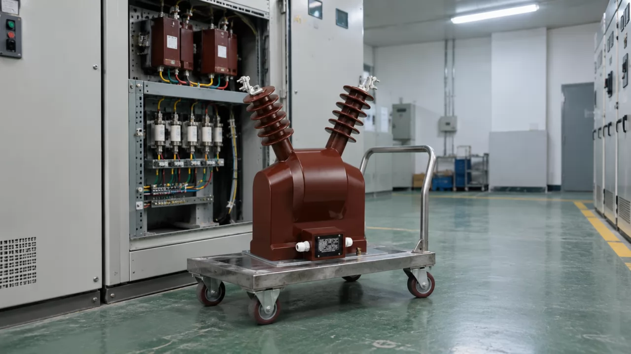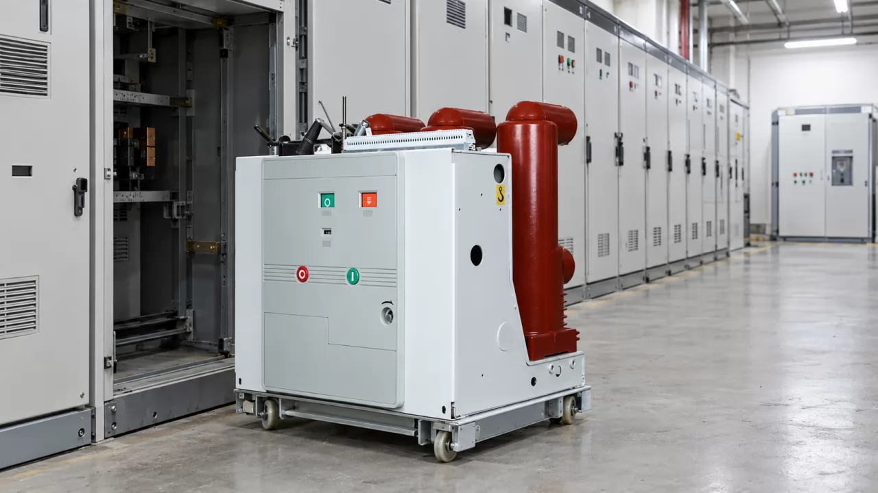
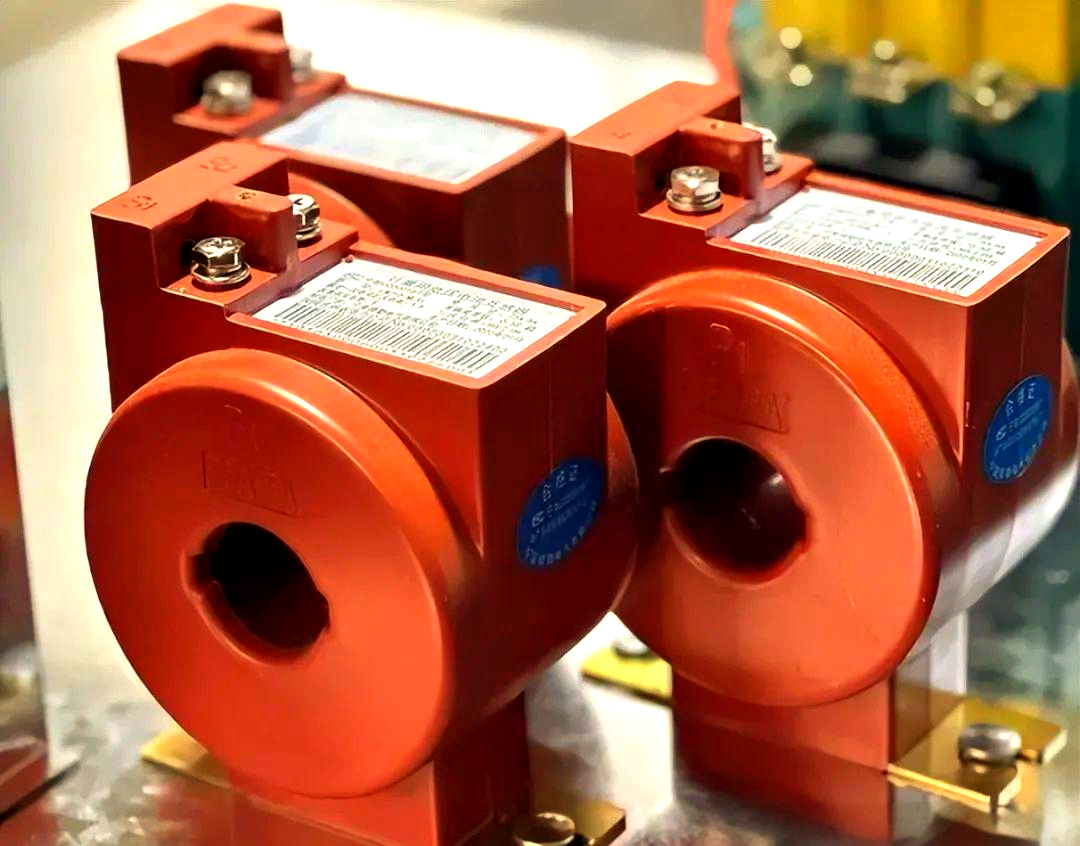
The CT on the incoming feeder says 0.2S on its nameplate, and the acceptance test still puts it outside tolerance. Much of the trade reads that class as the accuracy you will get on site. It isn't. The limitations of current transformers mostly come from conditions of use and from the circuit around the device. They are rarely factory defects, which is why a replacement unit often fails the same test.
What are the disadvantages of current transformers? The short answer before you specify one
A current transformer's main disadvantages are conditional accuracy, saturation that behaves differently in metering and protection cores, residual magnetism from past faults, sensitivity to wiring and secondary burden, and exposure to magnetic tampering. Each one stays hidden on the datasheet. Each one becomes visible at a predictable stage of the project's life.
The blunt version: a CT is only as accurate as the secondary circuit you connect it to. That changes only when the installation actually matches the conditions the CT was tested under, meaning rated burden, a centred conductor, rated frequency and no stray fields.
A current transformer (CT) is an instrument transformer that produces a secondary current proportional to the primary current, so meters and relays can measure high currents safely. The proportion is never exact. Two errors define it: ratio error (the magnitude is off) and phase angle error (the timing is off). Both are guaranteed only inside a test envelope.
Most of the trouble comes from five mechanisms:
accuracy that depends on secondary burden and site geometry
opposite saturation behaviour in metering and protection cores
remanence that shifts the saturation point after a fault
secondary current rating and cable length interacting badly
iron cores that an external magnet can push into saturation
None of these is unusual. What catches people out is timing. A wrong burden calculation shows up at acceptance. A mixed-up core type may stay quiet for ten years and then show up during a short circuit. A split-core unit can pass on day one and drift for the rest of its life. The table below puts each limit at the stage where it usually shows up, so you can see which ones cost money early and which cost money late.
| PROJECT STAGE | LIMITATION THAT SURFACES | WHAT IT COSTS YOU |
|---|---|---|
| Site acceptance | Total burden exceeds rating | Failed test, rework, delayed handover |
| Commissioning | 5A secondary on long cable runs | Saturation, re-cabling or CT replacement |
| First fault | Metering core used for protection | Relay fails to trip, equipment damage |
| Repeat faults | Remanence in the core | Earlier saturation, unpredictable relay response |
| Long-term operation | Split-core air gap drift | Billing disputes, unusable energy data |
| Settlement metering | Magnetic tampering of iron core | Under-reading, revenue loss |
Read down the right-hand column. The early costs are annoying but cheap to fix. The late ones (relay failure, revenue loss) are the ones a specification should prevent, because by then nobody connects the problem to the CT purchase order.
The limitations of current transformers start in the secondary loop, not the core
The result you want is simple to describe. A CT that passes site acceptance, stays inside its class for years, and gives the relay a clean signal on the one day it matters. Almost every factor behind that result sits outside the CT housing: the cable, the terminals, the meters and relays in series, the position of the busbar. The core itself is usually the most predictable part of the system.
Current transformer accuracy class is a conditional rating
An accuracy class such as 0.2S or 0.5 is a statement about test conditions. It holds at rated secondary burden. The primary conductor is centred in the window, the frequency is at its rated value, no external stray magnetic field is present, and the temperature sits inside the rated band. Change any of these and the guarantee no longer applies.
Two details are often missed. First, under IEC 61869-2 the metering classes define limits across a band of burden, typically from about 25% to 100% of rated burden. A CT can fall out of class from being underloaded as well as overloaded. Second, the "S" in 0.2S extends the accuracy guarantee down to about 1% of rated current, where plain 0.2 starts at about 5%. On a feeder that runs lightly loaded at night, that difference decides whether the energy figures are usable.
So a CT has no fixed accuracy. Its accuracy is a function of the secondary load.
Site conditions quietly use up the accuracy margin
The factory test fixture is tidy. Switchgear is not.
A busbar sitting off-centre in the CT window concentrates flux on one side of the core. Several conductors running side by side put the field from a neighbouring phase into the core. Long secondary cables add resistance. Terminals that oxidise over a few years add contact resistance that nobody measured during commissioning. None of this appears on the datasheet, and each item eats into the margin between the CT's actual error and its class limit.
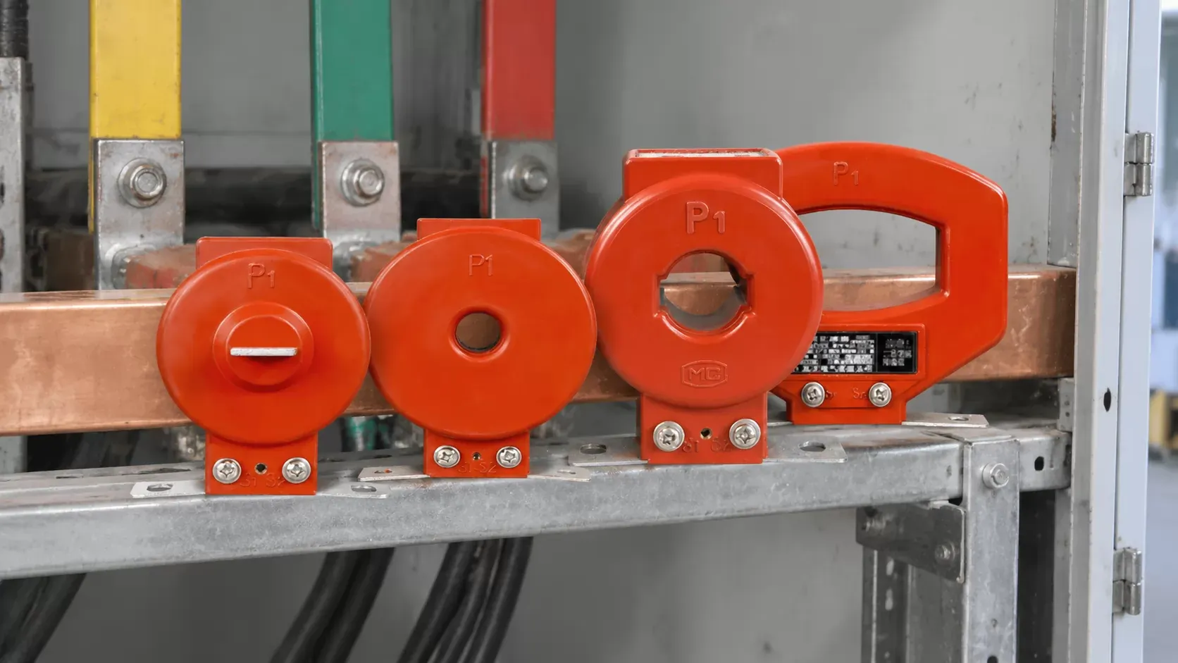
Commissioning engineers generally check burden and ratio with the CT installed, not on the bench, for exactly this reason. A bench test tells you the core is sound. Only an in-situ test tells you the installation is.
Add up the total burden before you compare accuracy classes
When a project fails acceptance, the CT is often fine. The cause is usually a selection made on accuracy class alone, without the full secondary load being totalled. The fix costs almost nothing: add every element of the loop and compare the sum with the burden rating, in volt-amperes (VA).
The sum has four parts. The meter or relay input burdens, taken from their own datasheets. The cable resistance over the full loop, out and back. Then contact resistance at every terminal and test block, and any auxiliary devices such as transducers or summation CTs. Cable resistance converts to burden as the square of secondary current times loop resistance, which is why the secondary rating matters so much (more on that in the 5A/1A comparison).
A sensible target is a total that lands comfortably inside the rated band, neither near the top nor below the lower limit. If you send an RFQ to a manufacturer such as Weisho Electric, include the cable route length, conductor size and the list of devices on each core. A quote sized to the installation is worth more than one sized to the nameplate.
Watch one trap while you add things up. Modern electronic meters often present a very small burden, sometimes well under 1 VA. Fit them to a CT rated 15 VA and the loop may sit below the lower burden limit. A metering CT running underloaded also saturates later than intended, so it protects the meter behind it less than its instrument security factor suggests.
5A and 1A secondaries force a trade-off between cable length and interference
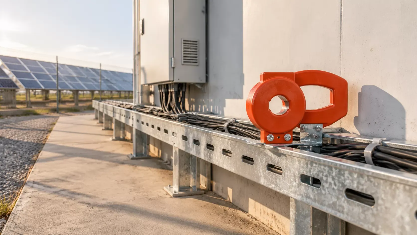
Burden from the cable equals current squared times resistance. At the same cable length and size, a 5A secondary therefore puts 25 times the line burden of a 1A secondary on the CT. That single fact explains a lot of commissioning failures on remote outdoor cabinets and on large sites where the relay room is far from the switchgear.
As a rough worked example, copper cable of 2.5 mm² has a resistance of roughly 7 mΩ per metre. A 50 m run means about 100 m of loop, or roughly 0.7 Ω. At 5A that loop alone consumes something like 17-18 VA, more than the full rating of many metering cores. At 1A the same cable takes well under 1 VA. The specification table below sets the two side by side.
| PARAMETER | 5A SECONDARY | 1A SECONDARY |
|---|---|---|
| Rated secondary current (A) | 5 | 1 |
| Relative cable burden, same cable | 25 | 1 |
| Approx. burden, 100 m loop of 2.5 mm² copper (VA) | 17-18 | about 0.7 |
| Secondary signal level | Higher | Lower |
| Sensitivity to drive and inverter harmonics | Lower | Higher |
| Typical fit | Short runs, legacy 5A instruments | Long runs, remote cabinets |
On long cable routes, 1A is usually the safer default. On short runs inside a noisy panel, 5A often holds up better.
Don't treat 1A as a universal answer, though. The lower signal level makes it more exposed to interference from variable-frequency drives and PV inverters. Those sources inject harmonics and switching noise into nearby wiring. Screened twisted cable and careful earthing reduce the problem, but they don't remove the trade-off. Neither rating is better in absolute terms. The choice is cable distance against interference exposure, and the transformer ratio has nothing to do with it.
Check one more thing before switching a project to 1A: every meter and relay on the loop has to accept a 1A input. Mixed retrofit sites sometimes keep 5A relays that nobody listed.
A CT is a current source, so wiring habits from 4-20mA sensors break it
Installers who work mostly with 4-20 mA transmitters carry a useful instinct into the wrong job. With a loop-powered transmitter, a longer cable means some signal attenuation and maybe a larger supply voltage. With a CT, the logic runs the other way.
A CT behaves as a current source. It forces the secondary current through whatever impedance it finds. To do that it has to build a voltage across the loop, and building that voltage needs magnetic flux in the core. Every extra ohm in the circuit demands more voltage and more flux, which pushes the core toward its saturation knee. The secondary impedance therefore decides whether the CT can drive its load at all.
In practice, three habits cause trouble. Adding another meter in series "because there's spare capacity" is one. Extending a cable to reach a relocated panel is another. A third is fitting a cheap terminal block with poor clamping. Each one raises the burden. None of them shows up until the next accuracy test or the next fault.
The current-source behaviour also creates a real safety hazard. An open secondary circuit has effectively infinite impedance, so the CT tries to drive its current through it by raising the voltage until the core saturates hard. The resulting peaks can reach dangerous levels, enough to injure someone and damage insulation. (Never open a CT secondary while the primary is energised. Short the secondary at the test block first, and keep shorting links in place during any meter change.) Inspection checklists for panels usually include confirming that every unused CT core is shorted and earthed before energisation.
Current transformer saturation works in opposite directions for metering and protection cores
CT saturation is the point where the core cannot carry more flux, so the secondary current stops following the primary and collapses into distorted pulses. Metering and protection cores are designed to reach that point at very different moments, on purpose.
A metering core is built for linearity at normal load and good accuracy at small currents. During a fault it is meant to saturate early, which limits the current reaching the meter and protects it. The instrument security factor, written as FS5 or FS10, expresses roughly how far above rated current that saturation begins at rated burden.
A protection core does the reverse. It has to stay linear through the first cycles of a short circuit so the relay sees the true fault current. A class such as 5P20 means the composite error stays within 5% up to 20 times rated current, again at rated burden.
Swap them and the failures are mirror images. A metering core feeding a relay saturates during the fault, the relay sees a fraction of the real current, and it may not trip. A protection core feeding a revenue meter stays linear at high current but carries larger errors at light load. The billing figures drift without anyone noticing.
Some panel builders fit one core type throughout to simplify stock and save cost. That is a latent risk. The panel passes routine tests, energy readings look plausible, and the problem stays invisible until a real short circuit. When you receive panels from a third-party assembler, compare the CT nameplates against the single-line diagram, core by core. Don't rely on the general arrangement drawing for this.
Remanence gives a CT a memory of its last fault
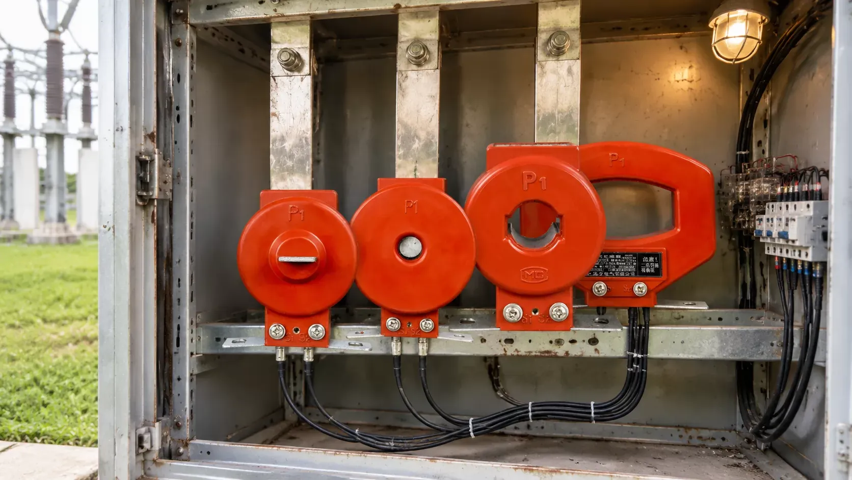
An iron core has magnetic hysteresis. When a short circuit drives it deep into saturation and the current is then interrupted, some flux stays behind. This residual flux is called remanence. The fault is gone and the load current is back to normal, but the core's flux no longer starts from zero.
The consequence shows up on the next fault. If that fault drives flux in the same direction as the remanence, the core has less headroom and reaches its saturation knee earlier. The same CT, facing two similar short circuits, can behave differently on each one. A relay set from the first event's behaviour may not see the second one the same way. Remanence fades very slowly under normal load and may persist for a long time.
Ordinary selection tables and catalogue pages almost never mention this behaviour. It is addressed in the transient performance classes of IEC 61869-2. Class TPX uses a closed core with no remanence limit. Class TPY includes small air gaps to restrict remanence. Class TPZ uses a gapped core with very low remanence. There are also PR classes, such as 5PR, that limit remanence for steady-state protection. Transient testing of this kind is normally specified for demanding substation duty such as line distance protection and fast auto-reclose schemes. If your project includes auto-reclosing, ask whether the protection cores carry a remanence-limited class. A standard 5P core does not.
Split-core CTs trade long-term accuracy for installation without an outage
Split-core (opening or clamp-on) CTs are popular for retrofit work because you can fit them without disconnecting the primary conductor. That convenience comes from a hinge or a separable joint in the core, and the joint is a permanent weakness.
Every joint is an air gap, and air has far higher magnetic reluctance than core steel. The gap increases magnetising current, which shows up as ratio and phase error. A closed core has no such gap. Worse, the gap does not stay constant. Dust settles on the mating faces, and vibration from nearby switchgear or transformers works the halves loose. Each time someone opens and closes the core, the surfaces wear a little more. The resulting error drift is cumulative. It does not recover by cleaning, and it cannot be calibrated out once and forgotten.
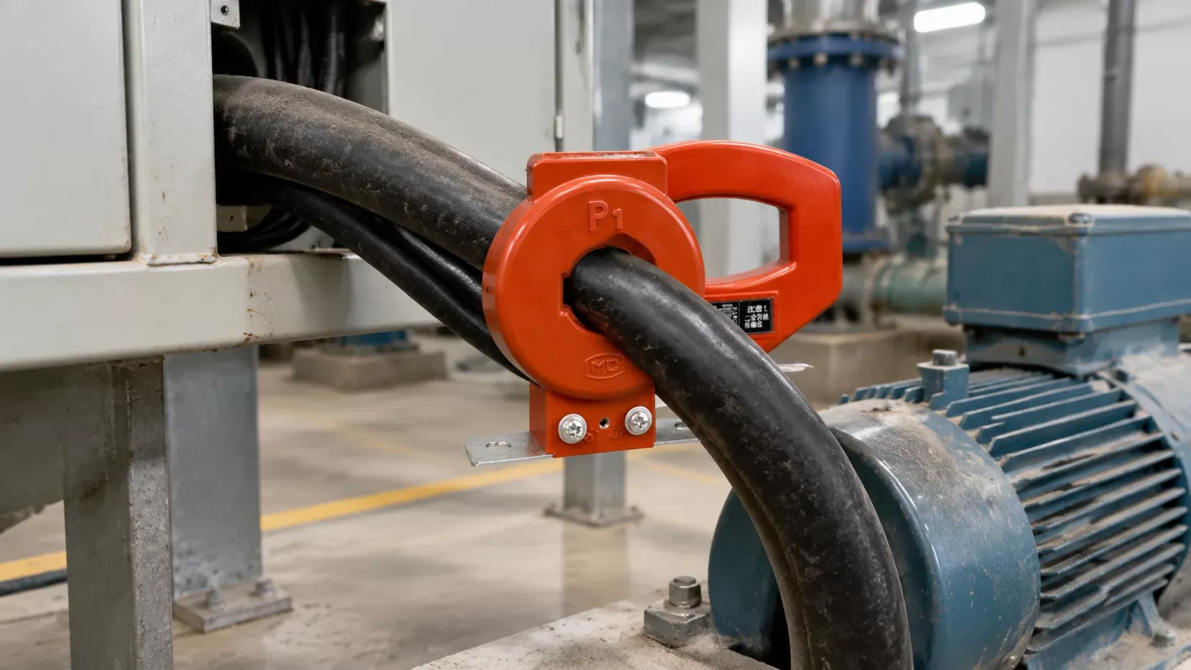
Even when a split-core unit carries a 0.2S marking, that figure may only hold at the first clean, perfectly seated fit. (If anyone proposes split-core units for revenue metering to save an outage, ask how the accuracy will be verified two years later. A clear answer is rare.) Treat split-core CTs as suitable for monitoring, energy management and load analysis. For trade settlement and billing-grade metering, plan the outage and fit a closed-core unit.
Quality checks are still worth doing on monitoring units: inspect the mating faces for burrs or coating on delivery, and check that the latch holds the halves under pressure.
Iron-core CTs can be forced into saturation with a magnet, a real weakness in settlement metering
An iron core responds to any magnetic field, including a static one from outside. A strong permanent magnet placed against the housing can bias the core toward saturation and pull the measured current down. For a protection CT inside a locked substation, this is a curiosity. In PV generation metering and electricity retail settlement, where meters sit in accessible cabinets, and the reading is money, it is a serious weakness.
Two alternatives avoid it. A Rogowski coil is an air-cored coil that measures the rate of change of current and uses an integrator to recover the current waveform. With no iron, it cannot saturate and does not react to a static magnet. An optical CT measures current through the Faraday effect, the rotation of polarised light in a magnetic field. It has no core to saturate and is often used in high-voltage digital substations. These properties help explain why iron-core units are being displaced in some renewable metering projects. The comparison below shows the main differences.
| CRITERION | IRON-CORE CT | ROGOWSKI COIL | OPTICAL CT |
|---|---|---|---|
| Static magnet tampering | Vulnerable | Not affected | Not affected |
| Saturation on fault current | Yes, core-dependent | None | None |
| Needs active electronics | No | Yes, integrator | Yes, optical interface |
| Relative cost | Lowest | Moderate | Highest |
| Best for | Conventional metering and protection | Retrofit, high current, tamper-sensitive sites | HV digital substations |
For most panels the iron-core CT remains the practical choice. Where settlement data could be tampered with, the extra cost of a Rogowski coil or optical CT often pays for itself in avoided disputes. Sealed covers and magnetic field detection on the meter are partial alternatives.
How to choose a current transformer for metering and protection without repeating these mistakes
Every limitation above can be addressed at the RFQ stage, before a single unit is wound. The specification should state the application of each core, the real burden, the cable route, the core construction, any transient duty and the tamper exposure at the installation site. The decision rules below cover the common forks.
If the core feeds a revenue meter, then specify a metering class (0.2S or 0.5S where light-load accuracy matters) with a suitable FS value, and keep it separate from any relay.
If the core feeds a relay, then specify a protection class such as 5P or 10P with an accuracy limit factor based on the calculated fault current and the actual burden.
If the cable run between the CT and the instruments is long, then calculate the loop burden and lean toward a 1A secondary, after confirming the instruments accept 1A.
If the scheme uses fast auto-reclose or distance protection, then ask for a remanence-limited class such as TPY, TPZ or a PR class.
If the meter is used for settlement and the cabinet is accessible, then consider a Rogowski coil or optical CT, or add tamper detection.
Split-core belongs in the specification only for monitoring duty. When a supplier such as Weisho Electric asks for the fault level, cable route and connected devices, that is a good sign. A quote without those questions is a quote for the nameplate, not for your site.
Standards tell you how a CT was tested, not how it will behave on your site
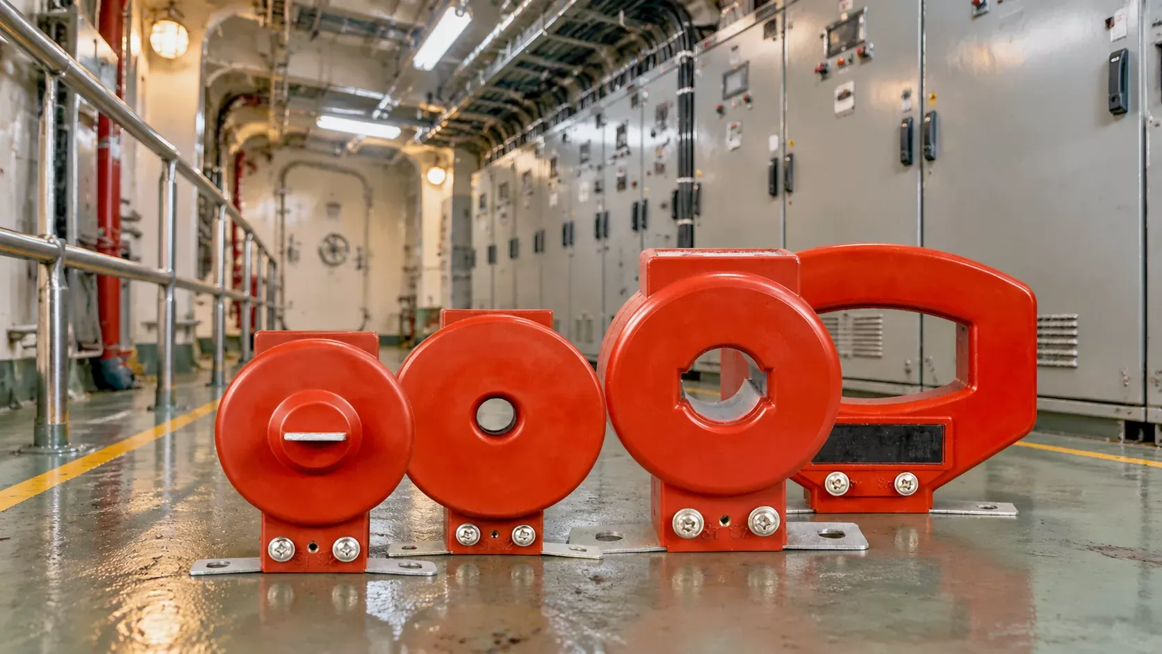
IEC 61869-1 sets the general requirements for instrument transformers: insulation, temperature rise, marking and routine and type testing. IEC 61869-2 covers current transformers specifically. It defines the metering classes (including 0.2S and 0.5S), the protection classes (P, PR, PX) and the transient classes TPX, TPY and TPZ. In North American markets, IEEE C57.13 plays the equivalent role, with its own accuracy and relaying class designations.
Compliance proves that a sample met these requirements under the conditions the standard prescribes: defined burden, defined conductor position, defined frequency and temperature. That matters, and you should ask for type test reports. But a compliant CT can still fall out of class on a site with an overloaded loop or an off-centre busbar. The standard says nothing about your cable.
Billing use may also require approval from the local metrology authority, and that approval sometimes covers the whole metering installation, not just the CT. Check the destination market's rules before the order is placed. Discovering a missing approval at the customs or commissioning stage is expensive.
The first thing to check on your next order: the real secondary burden
Before you compare prices, accuracy classes or lead times, get the burden calculation for the actual installation. Ask the panel builder or the end user for it, or build it yourself. List every meter and relay on each core, the cable size and route length, and the terminals in the loop. Then total the burden and compare it with the rated band. This one sheet of figures prevents most failed acceptance tests. It also exposes 5A-on-long-cable mistakes and tells you whether the protection core's accuracy limit factor will hold under fault current.
Quick answers to common CT questions
Can one CT serve both metering and protection?
No, not from a single core. A multi-core CT with separate metering and protection windings in one housing is the usual way to serve both duties.
Does buying a higher accuracy class make up for an oversized burden?
No. A 0.2S core loaded beyond its rated burden loses its class just as a 0.5 core does. Fix the burden first.
Is a split-core CT acceptable for billing-grade metering?
Generally no. Air-gap drift from dust, vibration, and repeated opening makes split-core units better suited to monitoring and load analysis.
How long can the secondary cable run before a 5A CT saturates?
Often only tens of metres. The limit depends on cable size, rated burden, and instrument load, so calculate the loop burden for each case.
Do Rogowski coils fully replace iron-core current transformers?
No. Rogowski coils avoid saturation and magnet tampering but need active integrators, and many existing relays and meters still expect a conventional CT input.
Rule of thumb: specify the loop first and the transformer second.