An isolation switch creates a visible open point, while a grounding switch connects the isolated circuit to earth so stored or induced voltage is safely discharged. If you read this article to the end, you will clearly understand the difference between the two, the operating sequence that keeps crews alive, and how to select the right combination for your actual working condition, whether you are dealing with AIS, GIS, transformer bays, cable feeders, or renewable collector systems.
What Is the Difference Between an Isolation Switch and a Grounding Switch?
The difference is practical, not semantic.
An isolation switch is used to provide visible separation from the power source. A grounding switch, also called an earthing switch in electrical substation practice, is used to connect the isolated part to earth for discharge and personnel protection.
In field work, I have seen crews assume that an open disconnector meant the cable was safe to touch. It was not. The visible break removed supply, but the conductor still held charge and also picked up induced voltage from adjacent energized circuits.
Why Confusing These Two Switches Causes Real Operational Risk
This confusion causes real incidents.
If you use an isolation switch where grounding is required, residual charge can remain on cables, capacitor banks, transformer windings, or GIS sections. If you use a grounding switch in the wrong sequence, you can create a fault event instead of a safe work condition.
Operators in practitioner discussions repeatedly describe the same pain points: rushed outage windows, pressure to bypass interlocks, misleading mimic diagrams, and the false belief that “open means dead.” That belief is one of the most dangerous habits in substation work.
The biggest risks are usually these:
Arc incidents from grounding an energized conductor
Trapped charge on cables, capacitors, and GIS compartments
Backfeed from transformers, VT circuits, generators, or secondary sources
Maintenance delays when interlocks prevent correction after an incorrect sequence
Failed lockout-tagout execution because switching status was assumed, not verified

Isolation Switch vs Grounding Switch at a Glance
| Item | Isolation Switch | Grounding Switch |
|---|---|---|
| Main function | Provide visible disconnection and system segregation | Connect the conductor/equipment to the earth |
| Primary safety purpose | Confirm isolation from the source | Discharge residual or induced voltage and protect personnel |
| Visible break | Yes, usually required and observable | Not the key feature |
| Load-breaking ability | Normally, no, unless specifically rated | No, except specific fault-making earthing switch designs |
| When operated | After de-energization or under undefined no-load conditions | After isolation and absence-of-voltage verification |
| Interlocking | Often interlocked with the breaker and the grounding switch | Strong interlocking is required to prevent closure on live circuits |
| Installation location | Line side, bus side, transformer bay, section points | Cable compartments, line bays, GIS sections, transformer terminals |
| Typical standard concern | Visible isolation, insulation distance, and no-load switching duty | Earthing duty, short-time current withstand, and interlock integrity |
What an Isolation Switch Does in High-Voltage Systems
An isolation switch is designed mainly for no-load isolation.
Its job is not to interrupt heavy current like a circuit breaker. Its job is to establish a safe and visible open gap so a section of the system can be separated for maintenance, testing, or system reconfiguration.
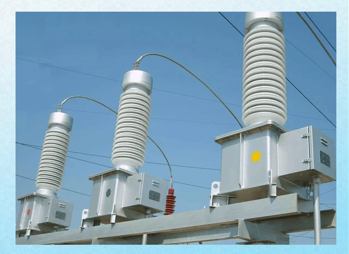
In AIS yards, the value is obvious because the operator can visually confirm blade position. In GIS, confirmation depends more on mechanical indication, gas compartment design, and strict interlocking logic.
High Voltage Isolation Switch Operation
High voltage isolation switch operation must follow one rule first: do not use it as a breaker unless the equipment is specifically rated for that duty.
Under IEC 62271 and corresponding IEEE switchgear practices, disconnectors are generally intended for opening and closing circuits when negligible current is switched, except for limited charging or transfer duties defined by rating.
Normal operating principles include:
Open the circuit breaker first
Verify the current path is de-energized
Operate the isolator under no-load conditions
Confirm mechanical position and visible isolation
Apply lockout/tagout before work begins
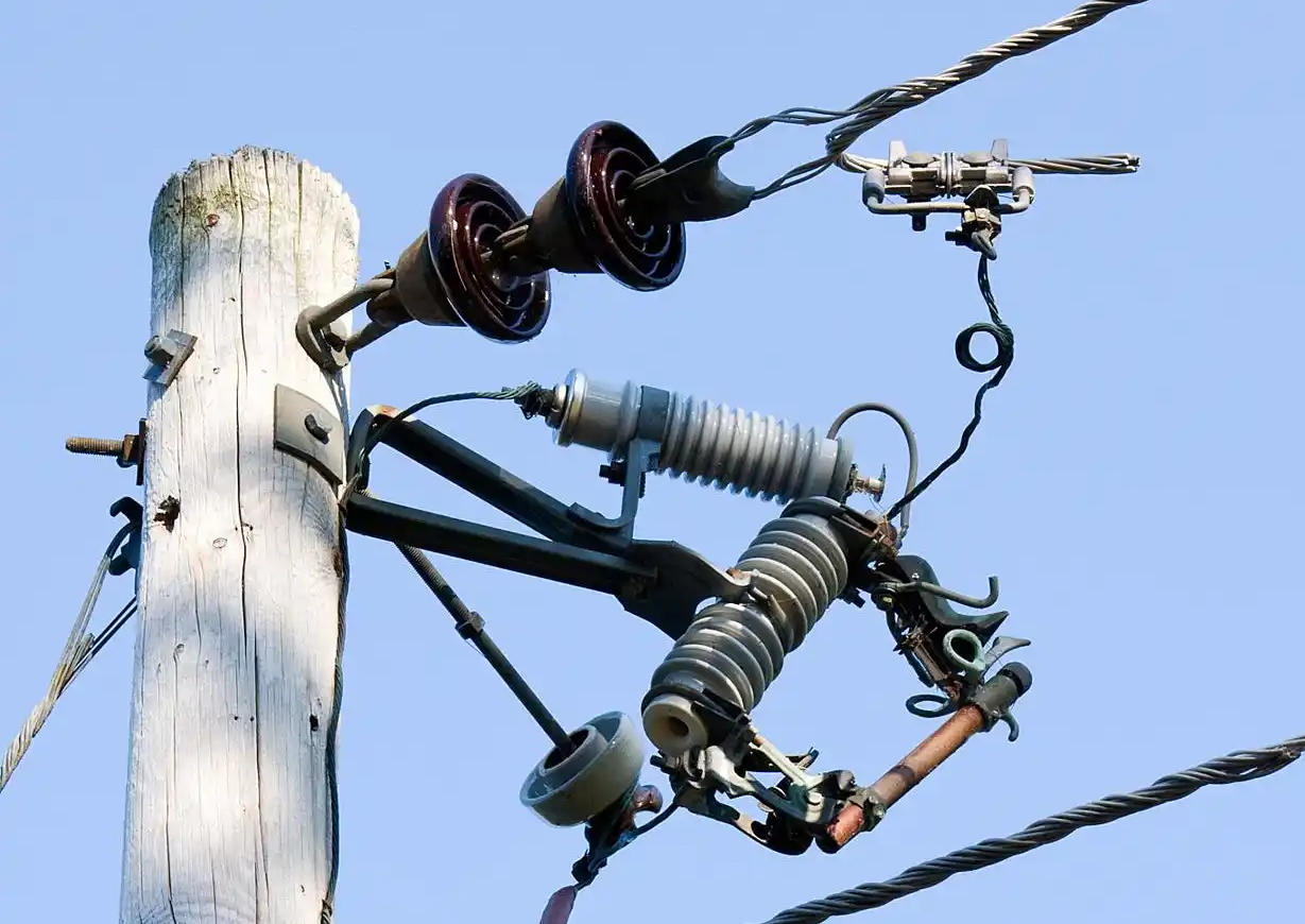
One field detail many non-specialists miss: on older outdoor disconnectors, linkage misalignment can show “open” locally while auxiliary indication to SCADA still reads uncertain or stale. Good crews trust both mechanical position and electrical indication, but they never rely on indication alone.
Disconnect Switch Safety Requirements
Disconnect switch safety requirements are simple on paper and unforgiving in real life.
Verify de-energization before operation
Apply lockout/tagout and permit-to-work control
Check the mechanical status indication locally
Confirm adequate clearance distance for the voltage class
Inspect interlocks before and after operation
Never treat a visible open as proof of zero voltage
IEEE and IEC guidance both reinforce the principle that isolation alone does not replace testing for absence of voltage and grounding where required by procedure.
What a Grounding Switch Does in Substations and Switchgear
A grounding switch is operated after isolation to create a deliberate bond to earth.
This discharges trapped energy, drains induced voltage, and protects maintenance personnel against unexpected energization. It is one of the final barriers between safe maintenance and serious injury.
In modern switchgear, the grounding switch may be separate or integrated. In either case, the functional question is the same: can the isolated part still hold or receive dangerous voltage? If yes, grounding is not optional.
Earthing Switch in Electrical Substation
An earthing switch in an electrical substation service is commonly installed on cable terminations, line bays, GIS enclosures, bus sections, and transformer-connected compartments.
It is operated after the circuit is opened and isolated, then verified dead. Once closed, it bonds the conductor to the station earth grid.
Why it matters is best understood from actual site experience. Long cable runs can retain capacitive charge longer than many expect. Parallel circuits can induce measurable voltage. Renewable plants can produce backfeed paths through collector systems, power electronics, and auxiliary transformers if the isolation plan is incomplete.
Switchgear Grounding and Isolation Procedures
Switchgear grounding and isolation procedures should be standardized and written into the work permit process.
The core sequence is:
1. De-energize the circuit
2. Open the breaker or load-interrupting device
3. Open the isolation switch
4. Verify absence of voltage
5. Close the grounding switch
6. Apply locks, tags, and work permit controls
Where utilities get into trouble is usually not ignorance of the sequence. It is a sequence drift under outage pressure. That is why mechanical and key interlocks matter so much.
Isolation Switch vs Grounding Switch: Functional Differences by Application
The same devices behave differently depending on the application.
| Application | Isolation Switch Role | Grounding Switch Role |
|---|---|---|
| AIS substation bay | Visible open point for line, bus, or transformer segregation | Ground isolated conductors before maintenance |
| GIS | Internal isolation with position indication and interlock logic | Earth GIS section after test for the absence of voltage |
| Transformer bay | Separate the transformer from the bus/line for the outage | Discharge windings and connected conductors to earth |
| Cable feeder | Isolate the cable section for testing or repair | Discharge cable capacitance and induced voltage |
| Busbar sectionalizing | Create a segregated bus section | Ground section before inspection or work |
| Renewable collector system | Separate feeder or array collector circuit | Control backfeed and induced voltage risk during service |

When to Use an Isolation Switch, a Grounding Switch, or Both
In real projects, the answer is often both.
| Scenario | Isolation Switch Needed | Grounding Switch Needed | Why |
|---|---|---|---|
| Transformer maintenance | Yes | Yes | Need visible separation and safe discharge of connected parts |
| Feeder shutdown | Yes | Usually yes | Backfeed and induced voltage risks are common |
| Capacitor bank work | Yes | Yes | Stored energy makes grounding essential |
| Cable testing | Yes | Yes | Cables retain charge and require controlled discharge |
| Busbar sectionalizing for configuration change | Yes | Not always | If no maintenance, grounding may not be required immediately |
Field-Proven Selection Criteria for Different Working Conditions
Selection should not start with catalog pages. It should start with the operating condition.
From project reviews and site commissioning work, the most reliable selection framework uses six variables:
Voltage level
Short-circuit and fault duty
Induced voltage or stored charge risk
Maintenance frequency
Interlocking complexity
Space and enclosure constraints
For example, on long MV and HV cable feeders, grounding becomes more important than inexperienced buyers expect. On compact GIS projects, integrated interlocks often justify a higher initial cost because they reduce switching error risk over the equipment's life.
Selection Table by Voltage Level and Site Condition
| Voltage / Site Condition | Recommended Isolation Configuration | Recommended Grounding Configuration | Notes |
|---|---|---|---|
| Distribution indoor switchboard | Load-break or isolating device as rated | Grounding point for feeder/cable work | Confirm local codes and maintenance method |
| MV cable feeder with a long run | Visible or positively indicated isolation | Dedicated grounding switch strongly recommended | High capacitive and induced voltage risk |
| HV AIS substation | Outdoor disconnect switch with a clear visible gap | Bay earthing switch with interlock | Best for maintenance visibility |
| HV GIS urban substation | Integrated GIS disconnector | Integrated earthing switch | Space-saving, high interlock dependency |
| Renewable collector station | Feeder isolation per bay | Grounding switch on the cable and equipment side | Backfeed paths must be carefully mapped |
Selection Table by Maintenance Task
| Maintenance Task | Isolation Requirement | Grounding Requirement | Priority Concern |
|---|---|---|---|
| Cable work | Mandatory | Mandatory | Stored charge and induced voltage |
| Breaker overhaul | Mandatory on both sides as applicable | Usually mandatory | Unexpected backfeed and adjacent energized parts |
| Transformer outage | Mandatory | Mandatory | Multiple energy sources and winding discharge |
| GIS inspection | Mandatory | Mandatory | Interlock integrity and compartment safety |
| Temporary shutdown, no physical work | Usually mandatory | Case dependent | Whether personnel access is planned |

Common Site Mistakes Engineers and Technicians Report
The same mistakes come up again and again in real field discussions.
Assuming visible open means discharged
Ignoring backfeed paths through transformers, VTs, generators, or coupled feeders
Changing the switching sequence under schedule pressure
Poor mimic panel labeling leading to bay confusion
Misunderstanding integrated switch-disconnector-earthing arrangements
One issue that rarely appears in theory documents but often appears in practice is unclear local versus remote status. Operators may see one indication in SCADA and another at the marshalling kiosk. That is why local confirmation at the device remains essential.
Real-World User Feedback and First-Hand Pain Points from Industry Discussions
Across industry discussions and site conversations, several recurring complaints stand out.
Outdoor mechanisms become stiff after dust, salt, or long idle periods. I have personally seen disconnect operating torque climb noticeably after one wet season in a coastal yard where routine exercising had been skipped.
Interlock bypass pressure is real during outage recovery. Teams under restoration deadlines sometimes try to “solve” a sequence problem mechanically instead of finding the true status conflict.
Induced voltage on long cables surprises people. This is especially common on parallel feeders and renewable collector circuits. Workers expect zero after isolation and are shocked when detectors still show a measurable presence.
Grounding blade verification in bad weather is difficult. Rain, fog, glare, and poor sight lines make visual confirmation harder than office procedures assume.
Integrated switchgear can confuse non-specialists. Some operators think a combined unit means every position provides the same safety function. It does not. Position logic matters.
Real Data and Incident Patterns That Matter for Decision-Making
The exact incident statistics vary by utility and region, but the failure patterns are remarkably consistent across audits, outage reviews, and manufacturer service reports.
| Failure Mode | Typical Cause | Operational Consequence | Preventive Control |
|---|---|---|---|
| Grounding switch closed onto live circuit | Sequence error, failed interlock, wrong bay identification | Arc event, equipment damage, crew injury risk | Hard interlocks, status verification, permit discipline |
| Isolator opened under load | The breaker failed to open, or the status was misunderstood | Arcing, contact damage, outage extension | Breaker position proof, current verification, procedure compliance |
| Residual charge remains after isolation | No grounding applied after disconnecting | Shock hazard, unsafe maintenance condition | Test for the absence of voltage and apply grounding |
| False open/close indication | Auxiliary contact mismatch, linkage misalignment | Unsafe switching decision | Local visual confirmation and periodic indication testing |
| Interlock cannot complete the sequence | Incorrect prior step or mechanical wear | Delay, attempted bypass, higher human error risk | Interlock maintenance and operator training |
Step-by-Step Safe Operating Sequence
This is the safe logic most facilities should follow, adapted to site procedure and equipment design.
| Step | Action | Purpose |
|---|---|---|
| 1 | Open the circuit breaker or designated interrupting device | Remove load and fault current duty from the path |
| 2 | Operate the isolation switch | Create visible or positively indicated separation |
| 3 | Verify the absence of voltage with the approved method | Confirm the isolated section is not energized |
| 4 | Close the grounding switch | Discharge residual energy and bond to the Earth |
| 5 | Apply locks, tags, and work permit controls | Maintain a safe work state |
| 6 | After work, remove grounds per procedure | Prepare for safe return to service |
| 7 | Close the isolation switch, then restore the breaker as directed | Re-energize in a controlled sequence |
Compliance, Standards, and Interlocking Considerations
Any selection or operating procedure should align with applicable utility rules and recognized standards.
For international projects, the most relevant references often include IEC 62271 series for high-voltage switchgear and controlgear, plus related IEEE switchgear and safety practices for disconnecting means, earthing, insulation coordination, and operational safety.
The standards consistently support four principles:
No-load switching limits for disconnectors unless specifically rated otherwise
Interlocking to prevent grounding of energized circuits
Visible or positively confirmed isolation
Permit-to-work and safety grounding controls
If a supplier cannot clearly state switching duty, short-time withstand current, making capacity for earthing function, and interlock philosophy, that is already a warning sign.
Best Practices for Maintenance, Inspection, and Reliability
Reliability is usually lost slowly before it is lost suddenly.
Check contact wear and overheating traces during planned outages
Inspect alignment of blades, jaws, and linkages
Lubricate drive mechanisms according to the environment and the manufacturer's interval
Test status indication locally and remotely
Verify the interlock function under the actual operating sequence
Exercise rarely used mechanisms, so they do not seize in emergency conditions
A very practical lesson from outdoor yards: equipment that sits untouched for years often fails exactly when the outage window is shortest. Preventive operation checks are cheap compared with the emergency restoration delay.

Isolation Switch and Grounding Switch FAQs
Can an isolation switch interrupt load current?
Normally, no. An isolation switch is generally intended for no-load operation and visible separation, not load interruption. Exceptions exist only where the device is specifically designed and rated for switching that duty, and the rating must be confirmed from the manufacturer and applicable IEC/IEEE requirements.
Why is a grounding switch required after isolation?
Because isolation removes the supply path, but it does not guarantee the conductor is fully discharged. Residual charge, induced voltage, and backfeed can still be present. The grounding switch bonds the isolated section to earth and provides personnel protection.
Can a grounding switch be closed on an energized circuit?
No, not in normal operation. It must not be closed onto an energized circuit unless it is a specifically rated fault-making earthing switch and the system design, protection coordination, and procedure explicitly allow that duty.
What is the correct sequence between disconnecting and grounding?
Isolate first, verify absence of voltage second, and apply grounding third. Opening the disconnector does not replace voltage verification, and grounding must only be applied after the circuit is proven de-energized according to procedure.
Is an earthing switch the same as a grounding switch?
Usually yes. The terms are commonly used interchangeably. The preferred term depends on region, manufacturer, and project documentation, but the function is the same: connecting the circuit or equipment to earth.
How do I choose between separate devices and an integrated switchgear solution?
Use footprint, interlock complexity, maintenance access, voltage class, environmental conditions, and lifecycle cost as the main decision factors. Integrated solutions are often better in compact GIS or urban substations, while separate devices can offer easier visual verification and simpler maintenance in AIS yards.
How to Choose the Right Switch for Your Operating Condition
The decision is straightforward when viewed by function.
Use an isolation switch when you need visible separation. Use a grounding switch when you need safe discharge and bonding to earth. Use both wherever maintenance safety, trapped charge, induced voltage, backfeed risk, or formal switching procedure requires a fully secure work condition.
If you remember only one thing, remember this: open is not the same as grounded, and isolated is not the same as safe to touch until the absence of voltage is verified and grounding is applied.
Need Help Matching the Right Isolation and Grounding Switch to Your Project?
If you want a precise recommendation, send us your voltage level, application, installation environment, and maintenance procedure. We can help you choose the right isolator switch vs grounding switch configuration, interlocking scheme, and switchgear arrangement for your project.
For product details, technical selection support, or a fast quotation, please send us an inquiry or contact us directly via WhatsApp.