In high-power converters, current sensing is never a trivial detail. It directly affects efficiency, thermal performance, protection speed, control accuracy, and even whether the design is practical to manufacture.
For many engineers, the most useful lesson is this: a current transformer (CT) can measure large AC or pulsed current with far lower loss than a shunt resistor, especially on the primary side of a switching power supply.
This article explains the current transformer calculation formula, the design process, the difference between a CT and a normal voltage transformer, and the real source of measurement error. It also walks through a complete 10A design example using only two core formulas.
Why Current Transformer Calculation Matters in High-Power Converters
In a power converter, the primary current often carries critical information. It is used for peak current mode control, overload protection, short-circuit detection, and power regulation.
The challenge is that direct sensing on a high-current path can waste real power. At low current, that may be acceptable. At 10A and above, it often becomes expensive in heat, board area, and efficiency.
This is why CTs are so valuable. A properly designed CT allows you to sense the primary current while keeping burden loss very low. That is the practical reason current transformers remain common in offline switch-mode power supplies, inverters, motor drives, and industrial power electronics.
In other words, the current transformer sizing guide is not just an academic exercise. It can determine whether your converter loses watts in the sense path or only milliwatts.
The Problem With Shunt Resistors for 10A Current Sensing
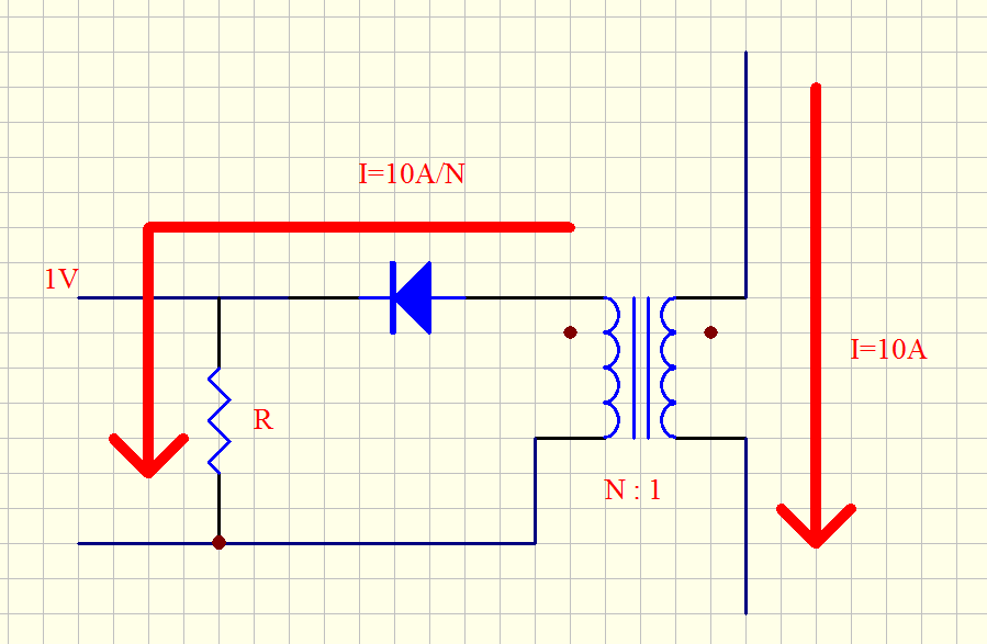
Let us start with a very concrete example. Suppose you want to detect 10A of primary current and obtain a useful signal level around 1V.
If you do this with a direct shunt resistor, the resistor value would be:
R = V / I = 1V / 10A = 0.1Ω
The power dissipated in that resistor becomes:
P = I²R = 10² × 0.1 = 10W
That is not a rounding error. That is a serious heat source.
A 10W shunt on the primary side of a converter means temperature rise, derating, larger PCB copper, and reduced efficiency. It may also force a physically larger resistor and introduce thermal drift concerns.
Now compare that with a CT-based sensing method. In the design example used throughout this article, the secondary burden power is only 50mW.
So the same 10A current information can be obtained with roughly:
10W loss using a direct shunt approach
50mW loss using a current transformer approach
That difference is why experienced power engineers reach for CTs in high-current primary sensing applications.
What a Current Transformer Really Does
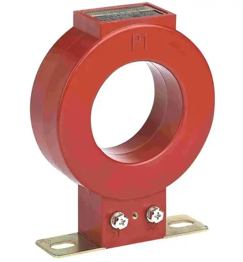
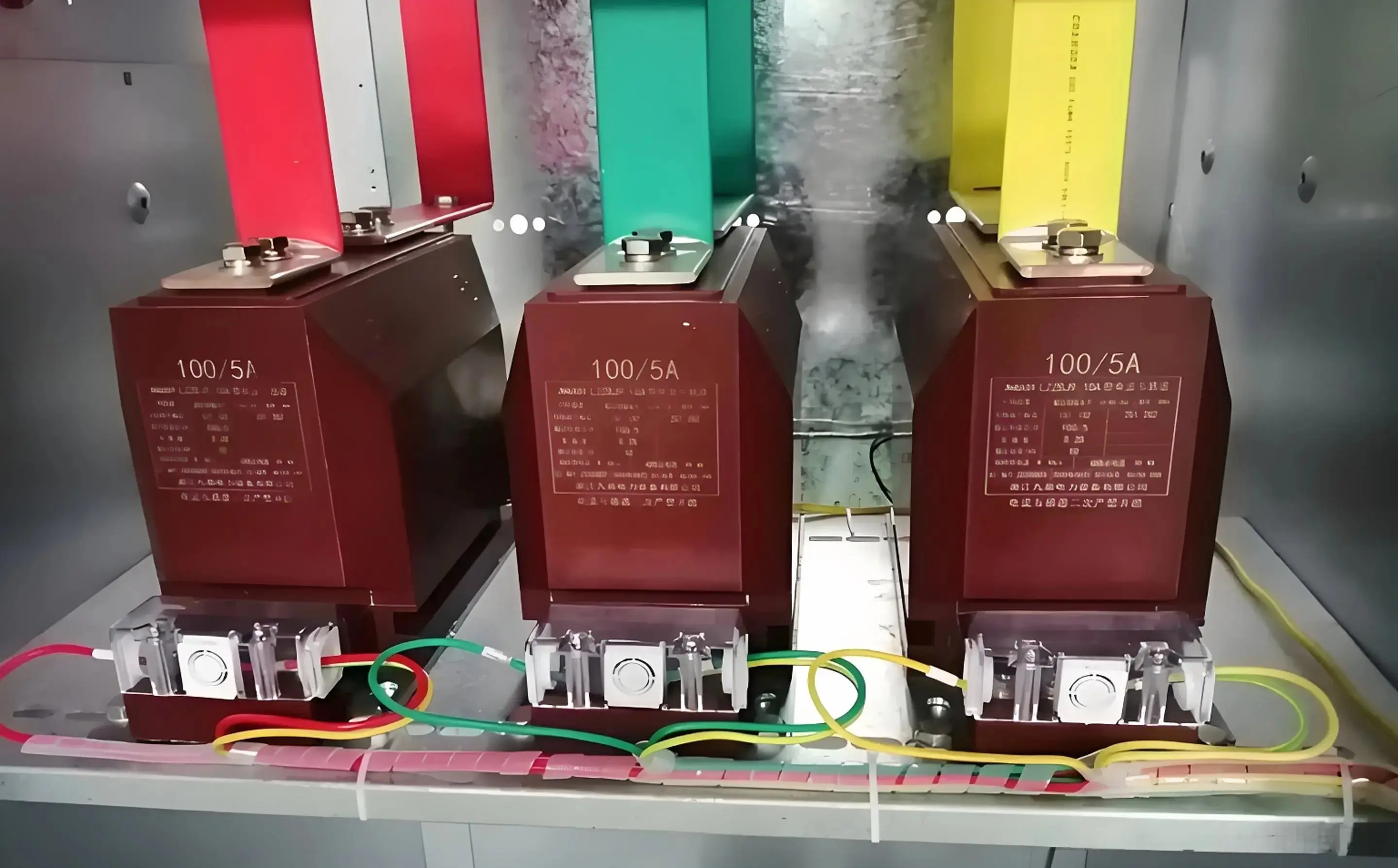
A current transformer does not behave like a normal voltage transformer. This is the first point that must be understood clearly.
A voltage transformer is typically driven by an applied voltage, and its turns ratio determines the secondary voltage. A current transformer is different: it is driven by primary current, and its secondary current follows the turns ratio relationship.
The secondary voltage of a CT is not fixed by the turns ratio alone. It is determined by the current flowing in the secondary loop and the impedance in that loop, especially the burden resistor.
That is why a CT can be understood as a special magnetic device where the current is the transformed quantity, while the resulting secondary voltage depends on the load.
In practical converter work, the primary is often just one turn—for example, the power conductor passed once through a toroidal core. The secondary may then have tens, hundreds, or more turns of fine wire, and the burden resistor converts the secondary current into a measurable voltage.
Current Transformer vs Voltage Transformer: The Key Difference
Many design errors start here. A normal voltage transformer cannot simply replace a current transformer in a current sensing circuit.
Why not? Because the driving condition is fundamentally different.
Voltage transformer: input is an applied voltage, output is a transformed voltage.
Current transformer: input is a forced current, output is a transformed current.
In a CT, the primary current is set by the power circuit. It is not determined by the voltage across the transformer terminals. The secondary current must balance primary ampere-turns, and the burden resistor converts that current into a voltage.
This is the reason you cannot take a small ordinary transformer meant for voltage conversion and assume it will behave properly as a current transformer. Its magnetizing inductance, intended operating mode, and accuracy behavior are not the same.
So one key conclusion of this article is simple: do not substitute a normal voltage transformer for a current transformer in precision current measurement.
The Only 2 Current Transformer Formulas You Need
For a practical converter sensing design, most of the core work can be done with just two equations. This is the reason CT design is often simpler than it first appears.
Formula 1: Current Transformer Turns Ratio Equation
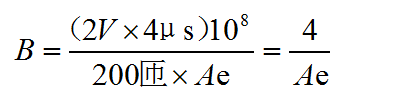
The first and most important equation is the ampere-turn balance:
Ip · Np = Is · Ns
Where:
Ip = primary current
Np = primary turns
Is = secondary current
Ns = secondary turns
This is the essential current transformer turns ratio equation. If the primary is 1 turn and the secondary is 200 turns, then the secondary current is 1/200 of the primary current, ignoring small error currents.
Formula 2: Minimum Secondary Inductance for Accuracy
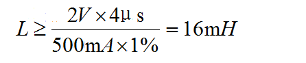
The second key equation controls error caused by magnetizing current:
Ls(min) = Vs / (f · Imag)
Where:
Ls(min) = minimum secondary magnetizing inductance
Vs = secondary winding voltage
f = operating frequency
Imag = allowable magnetizing current
This equation matters because magnetizing current does not pass through the burden resistor in the same useful way as transformed load current. If the magnetizing current is too high, measurement accuracy suffers.
Together, these two equations handle the practical questions behind how to calculate CT ratio and how to keep CT error under control.
Step-by-Step Current Transformer Calculation Example
Now let us apply the method to a realistic converter sensing case.
Design target:
Primary current Ip = 10A
Primary turns Np = 1
Target output voltage across burden resistor Vout = 1V
Desired burden power P = 50mW
This example is intentionally practical. The purpose is to sense 10A on the primary side of a switching power supply while avoiding the 10W loss that a direct shunt resistor would create.
Step 1: CT Burden Calculation Method for the Sense Resistor
First, calculate the burden resistor value from the output voltage and allowed burden power.
Rsense = Vout2 / P
Substitute the values:
Rsense = 12 / 0.05 = 20Ω
So the burden resistor should be 20Ω.
This is the practical CT burden calculation method used here. Instead of guessing a resistor, we choose the target voltage and burden power first, then derive the resistor value.
Step 2: Calculate Secondary Current
Next, find the required secondary current to produce 1V across 20Ω.
Is = Vout / Rsense
Substitute the values:
Is = 1 / 20 = 0.05A = 50mA
So the CT secondary current at 10A primary current must be 50mA.
Step 3: How to Calculate CT Ratio and Secondary Turns
Now use the ampere-turn balance:
Ip · Np = Is · Ns
Substitute the known values:
10A × 1 = 0.05A × Ns
Therefore:
Ns = 10 / 0.05 = 200 turns
This is the answer to both how to calculate CT ratio and the practical winding count for the example. The CT requires a 200-turn secondary when the primary is a single pass through the core.
Step 4: Check Magnetizing Current Error Limit
Assume the measurement error target is 1%. Then the magnetizing current should be no more than 1% of the useful secondary current.
The useful secondary current is 50mA, so:
Imag = 50mA × 1% = 0.5mA = 500μA
This is a very important checkpoint. If the core and winding do not provide enough inductance, the magnetizing current rises and starts stealing current that should otherwise appear in the burden resistor.
That missing current becomes measurement error.
Step 5: Calculate Minimum Secondary Inductance and Core AL Value
Now apply the second core equation:
Ls(min) = Vs / (f · Imag)
In this example, the secondary winding voltage is approximately the burden voltage, so use Vs ≈ 1V.
The exact frequency depends on the converter. To make the method concrete, let us use a realistic switching frequency of 100kHz.
Then:
Ls(min) = 1 / (100,000 × 0.0005) = 20mH
So the secondary inductance should be at least 20 mH to keep the magnetizing current at or below 500 μA under these assumptions.
Next use:
Ls = Ns2 · AL
Rearrange for core AL value:
AL = Ls / Ns2
Substitute the values:
AL = 20mH / 2002 = 0.02 / 40,000 = 5 × 10⁻⁷ H/turn²
That is:
AL = 500nH/turn²
This is not an extreme requirement. In practice, a normal ferrite toroid can often satisfy it, which is why the original engineering conclusion is that ordinary ferrite ring cores are usually sufficient for this kind of design.
Example Data Table: Full CT Design Calculation
| Parameter | Symbol | Value | Unit | Meaning |
|---|---|---|---|---|
| Primary current | Ip | 10 | A | Current to be measured |
| Primary turns | Np | 1 | turn | Single-pass primary conductor |
| Target output voltage | Vout | 1 | V | Voltage across burden resistor |
| Burden power | P | 0.05 | W | Secondary power dissipation target |
| Burden resistor | Rsense | 20 | Ω | Calculated from Vout2/P |
| Secondary current | Is | 0.05 | A | 50mA secondary current |
| Secondary turns | Ns | 200 | turns | From ampere-turn balance |
| Error target | - | 1 | % | Maximum current measurement error |
| Allowed magnetizing current | Imag | 500 | μA | 1% of 50mA |
| Example switching frequency | f | 100 | kHz | Used for inductance estimate |
| Minimum secondary inductance | Ls(min) | 20 | mH | From Vs/(f·Imag) |
| Required core AL | AL | 500 | nH/turn² | From L/N² |
Comparison Table: Shunt Resistor vs Current Transformer Sensing
| Criteria | Direct Shunt Resistor | Current Transformer |
|---|---|---|
| Example current | 10A | 10A primary, 50mA secondary |
| Typical signal target | 1V | 1V across burden resistor |
| Power loss in example | 10W | 50mW |
| Heat generation | High | Very low |
| Isolation capability | None by itself | Can provide galvanic isolation |
| Efficiency impact | Severe at high current | Minimal |
| PCB space for power dissipation | Large | Small |
| Best use case | Low current or DC sensing | High-current AC or pulsed current sensing |
Do Diodes and Winding Resistance Affect CT Measurement Accuracy?
This point is often misunderstood in practical designs.
If a diode is placed in series with the CT secondary loop, or if the winding has some copper resistance, these do not directly change the measured current ratio in the ideal operating region. What they mainly change is the voltage required across the CT secondary to force the loop current through the entire series path.
In a series loop, the same current flows through all series elements. So the burden resistor current remains the same loop current as long as the CT can supply the needed voltage without violating its magnetic limits.
That means a Schottky diode with lower forward drop is mainly beneficial because it reduces the voltage stress that the CT secondary must develop. It eases magnetic operating conditions, but it does not magically change the burden current ratio itself.
Likewise, winding resistance only adds to the total voltage drop in the secondary loop. It does not directly alter the current measurement value unless the added voltage demand pushes the core toward insufficient inductance or other non-ideal behavior.
This is why the original engineering point is correct: series diode drop and winding resistance mainly change CT internal voltage conditions, not the intended current relationship.
Where CT Error Really Comes From
In this kind of design, the main error source is not usually the diode drop or the copper resistance. The real issue is magnetizing inductance.
A real CT requires some current to magnetize its core. That current is the magnetizing current. It does not fully appear as useful output current in the burden resistor.
So if the ideal transformed secondary current should be 50mA, but 500μA is consumed as magnetizing current, only the remainder contributes properly to the burden output. That creates about 1% measurement error.
This is the central accuracy mechanism in CT design. If the secondary inductance is too low, magnetizing current increases. If magnetizing current increases, the sensed output no longer matches the ideal turns-ratio result closely enough.
That is why the second formula matters so much. It turns a vague requirement like “keep the CT accurate” into a clear engineering constraint on minimum secondary inductance.
Current Transformer Sizing Guide for Core and Wire Selection
Many engineers assume core selection is mostly about saturation and core loss. In this specific 10A, 200-turn sensing example, that is often not the first limitation.
In practice, the core size may be chosen more by isolation requirements and winding space than by saturation.
Core Selection Based on Isolation and Winding Window
If galvanic isolation is required between the primary conductor and the secondary winding, then creepage, clearance, insulation system, and physical spacing can dominate the geometry choice.
If no isolation is required, the design may still be limited by the need to physically fit 200 turns of wire around the core without making winding difficult or inconsistent.
For this reason, a very small core is not always a good answer even if the magnetic calculations say the AL target is easy to meet. Mechanical winding practicality matters.
In actual production work, teams often select a ferrite toroid that gives enough window area, enough insulation margin, and a comfortable AL value, rather than chasing the absolute smallest magnetic part.
This is also where a capable magnetic component supplier can help. For example, when discussing custom current-sensing magnetics with Weisho Electric, engineers typically focus not just on turns ratio, but also on insulation structure, winding process consistency, and real manufacturability.
Wire Gauge Limits for Practical Winding
Very fine wire is tempting because 200 turns sound like a lot. But there is a practical limit.
A useful rule in this example is that wire finer than about 36 AWG is usually not recommended. Below that, handling becomes more difficult, breakage risk increases, and production consistency can suffer.
So if the 200-turn secondary does not fit with a practical wire gauge, the answer is often to select a slightly larger core rather than pushing the wire too fine.
Common CT Design Mistakes to Avoid
Most CT problems in converter sensing come from a small set of avoidable mistakes.
Using a normal voltage transformer as a CT. This is the wrong operating principle.
Ignoring burden power. If the burden is chosen carelessly, the output voltage and loss targets will not be met.
Undersizing secondary inductance. This increases magnetizing current and creates ratio error.
Forgetting that secondary voltage is load-dependent. The burden resistor and any series diode define the required secondary voltage.
Choosing core size only from magnetic theory. Winding window and isolation often matter more in this class of design.
Using excessively fine wire. This creates manufacturing and reliability problems.
Assuming diode drop changes measured current directly. It usually changes required secondary voltage, not the intended series current.
If you avoid these mistakes, most CT designs for converter current sensing become straightforward.
Quick Reference Table: Formulas and Variable Definitions
| Formula | Symbol | Definition | Unit | Design Meaning |
|---|---|---|---|---|
| Ip · Np = Is · Ns | Ip | Primary current | A | Input current being measured |
| Ip · Np = Is · Ns | Np | Primary turns | turn | Often 1 in primary current sensing |
| Ip · Np = Is · Ns | Is | Secondary current | A | Current through burden resistor |
| Ip · Np = Is · Ns | Ns | Secondary turns | turn | Determines current ratio |
| Ls(min) = Vs / (f · Imag) | Ls(min) | Minimum secondary inductance | H | Needed to limit magnetizing-current error |
| Ls(min) = Vs / (f · Imag) | Vs | Secondary winding voltage | V | Approximate loop voltage required |
| Ls(min) = Vs / (f · Imag) | f | Operating frequency | Hz | Converter switching frequency or sensed current frequency |
| Ls(min) = Vs / (f · Imag) | Imag | Allowed magnetizing current | A | Sets error budget |
| Rsense = Vout2 / P | Rsense | Burden resistor | Ω | Used to convert CT current to voltage |
| Is = Vout / Rsense | Vout | Output voltage across burden resistor | V | Signal delivered to the control circuit |
| Ls = Ns2 · AL | AL | Core inductance factor | nH/turn² | Used to select suitable core material and geometry |
Key Takeaways From the 10A CT Design Example
This example gives several practical conclusions that are easy to reuse in real projects.
Formula 1: Current Transformer Turns Ratio Equation
A direct 10A shunt with 1V output wastes about 10W.
A CT solution can reduce that sensing loss to about 50mW.
The burden resistor for the example is 20Ω.
The required secondary current is 50mA.
With a 1-turn primary, the secondary requires 200 turns.
For 1% error, magnetizing current should stay at or below 500μA.
At 100kHz and 1V secondary, the minimum secondary inductance is about 20mH.
The required AL value is about 500nH/turn², which ordinary ferrite toroids can often provide.
Diode drop and winding resistance mainly affect required CT voltage, not the current ratio directly.
The biggest accuracy risk is insufficient magnetizing inductance.
So if you remember only one thing, remember this: the CT ratio sets the current, and the magnetizing inductance sets the accuracy.
FAQ
How do you calculate current transformer ratio?
Use the ampere-turn balance equation: Ip · Np = Is · Ns. For example, if the primary current is 10A, the primary turns are 1, and the desired secondary current is 50mA, then the secondary turns are 10 / 0.05 = 200 turns.
What is the current transformer calculation formula for secondary current?
The core formula is Ip · Np = Is · Ns. Solving for secondary current gives Is = (Ip · Np) / Ns. If 10A flows in a 1-turn primary and the secondary has 200 turns, then the secondary current is 10 / 200 = 50mA.
How do you calculate CT burden resistor value?
Use Rsense = Vout2 / P when you know the desired output voltage and allowable burden power. In this example, 1V output and 50mW power give Rsense = 1² / 0.05 = 20Ω. Then you can find secondary current from Is = Vout / Rsense.
Why can’t a normal voltage transformer replace a current transformer?
A normal voltage transformer is designed to transform voltage from a voltage-driven input. A current transformer is designed to transform current from a current-driven primary. In a CT, the secondary voltage depends on the burden, so the operating principle is fundamentally different.
Does a Schottky diode affect CT current measurement?
A Schottky diode changes the voltage conditions in the secondary loop because it adds forward drop, although less than a standard diode. However, it does not directly change the series loop current ratio as long as the CT can still generate the necessary voltage and stay within its magnetic operating limits.
What causes current transformer measurement error?
The main cause is insufficient magnetizing inductance. If inductance is too low, magnetizing current increases, and part of the transformed current no longer appears properly through the burden resistor. That missing current shows up as measurement error.
How do you choose the core for a current transformer?
Choose the core based on three practical requirements: the needed AL value for minimum inductance, the physical space needed to fit the required turns, and the isolation or insulation requirements of the application. In many converter designs, winding window and isolation are more limiting than core saturation.
Conclusion and Next Step
For practical converter current sensing, CT design is much simpler than many engineers expect. In most cases, only two formulas carry the core work: the turns-ratio equation for current scaling, and the minimum inductance equation for accuracy control.
The 10A example proves the value clearly. A direct shunt can waste about 10W, while a properly designed CT can reduce sensing loss to about 50mW. That is a major gain in efficiency, heat reduction, and overall design elegance.
Just as important, the example shows what really matters in a good design. The burden resistor determines output voltage, the turns ratio determines secondary current, and the magnetizing inductance determines whether the measured value remains accurate.
If you are working on a switching power supply, inverter, or any high-current converter, this approach is one of the most effective ways to sense primary current without paying a heavy efficiency penalty.
Ready to calculate your own CT design?
Start with your real primary current, target output voltage, allowable burden loss, and acceptable error budget. Then use the two formulas in this guide to verify the turns ratio, burden resistor, minimum secondary inductance, and required core AL value.
If you are designing a real product, do not guess. Check the burden loss, confirm the 1% error limit, verify winding space for the required turns, and make sure the core supports the needed inductance.
Take the next step now: calculate your CT, validate your numbers, and request engineering support for selecting the right turns count, burden resistor, wire gauge, and magnetic core for your actual converter.