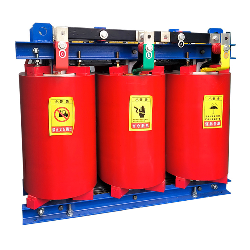

A step-up transformer raises voltage from the primary side to the secondary side, while a Step-Down Transformer lowers voltage from the primary side to the secondary side.
That is the simplest answer, but in real electrical systems, the difference affects safety, current, insulation design, wire size, equipment reliability, and operating cost. If you work with power distribution, industrial machinery, renewable energy, consumer electronics, or utility infrastructure, understanding this distinction is not optional.
In practical engineering, the transformer is rarely just a box that changes voltage. It is a system-level decision that influences losses, thermal behavior, compliance, and end-user safety.
This guide explains the difference between step-up and step-down transformers, the step-up transformer working principle, step-down transformer applications, the relationship between transformer voltage ratio and turns ratio, and a complete power transmission transformer comparison grounded in real-world examples.
What Is the Difference Between a Step-Up Transformer and a Step-Down Transformer?
A step-up transformer converts a lower input voltage into a higher output voltage. It does this by using more turns in the secondary winding than in the primary winding.
A step-down transformer does the opposite. It converts a higher input voltage into a lower output voltage by using fewer turns in the secondary winding than in the primary winding.
In short:
Step-Up Transformer: increases voltage, decreases current approximately in inverse proportion
Step-Down Transformer: decreases voltage, increases current approximately in inverse proportion
Step-up design: secondary turns > primary turns
Step-down design: secondary turns < primary turns
This core difference is easy to state, but what matters in real use is how it changes conductor sizing, insulation requirements, losses, and equipment suitability.
Why Understanding Step-Up Transformer vs Step-Down Transformer Matters
Choosing the wrong transformer can create serious problems. Sometimes those problems are immediate, such as burned devices or nuisance tripping. Other times they appear slowly, through heat stress, insulation degradation, or poor energy efficiency.
For example, if a 120 V control circuit is accidentally supplied from a transformer intended to step voltage up instead of down, the downstream electronics may fail instantly. In industrial panels, that mistake can destroy relays, PLC input modules, and low-voltage contactor coils in seconds.
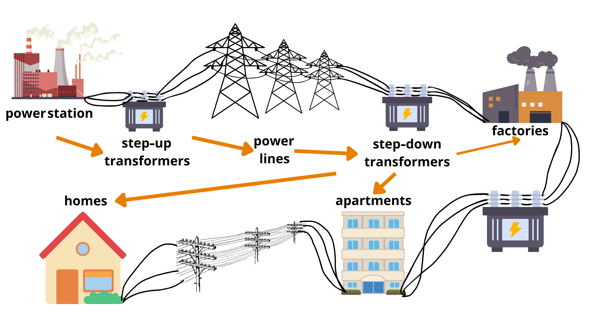
In utility systems, the consequences are even larger. Long-distance transmission at low voltage would cause massive current flow and unacceptable I²R losses. That is why generating stations use step-up transformers before power enters high-voltage transmission networks.
At the user end, the reverse is true. Homes, offices, and commercial buildings need usable and safer voltages. Without step-down transformers, grid voltage would remain far too high for lighting circuits, appliances, electronics, and building services.
Understanding the difference matters for these reasons:
Safety: the wrong voltage can damage people and equipment
Efficiency: transformer selection directly affects losses and heat
Performance: motors, chargers, and control circuits require correct voltage
Compliance: electrical systems must meet code and equipment standards
Cost: bad transformer sizing increases operating and maintenance expense
In real projects, experienced engineers also consider ambient temperature, duty cycle, harmonics, inrush current, insulation class, and fault tolerance. That is where product quality matters, and where a specialized manufacturer such as Weisho Electric can stand out by focusing on application fit rather than generic catalog claims.
Step-Up Transformer Working Principle
The step-up transformer working principle is based on electromagnetic induction. When alternating current flows through the primary winding, it produces an alternating magnetic flux in the transformer core.
This changing magnetic flux links the secondary winding and induces an electromotive force. If the secondary winding has more turns than the primary winding, the induced secondary voltage becomes higher than the primary voltage.
This is not a mystery effect. It follows directly from Faraday’s law and the proportional relationship between induced voltage and the number of turns in the winding.
In an ideal transformer:
V1 / V2 = N1 / N2
Where:
V1 = primary voltage
V2 = secondary voltage
N1 = number of turns in primary winding
N2 = number of turns in secondary winding
If N2 > N1, then V2 > V1. That is the defining behavior of a step-up transformer.
A familiar example appears in renewable energy. Many solar inverter systems condition and transform power before connection to a medium-voltage collection network. A low inverter output may be stepped up to several kilovolts for efficient plant-level distribution.
Transformer Voltage Ratio and Turns Ratio
The transformer voltage ratio and turns ratio are directly proportional in ideal operation. This is one of the most important concepts in transformer design and transformer troubleshooting.
The formula is:
V2 / V1 = N2 / N1
If a transformer has 100 turns on the primary and 500 turns on the secondary, the turns ratio is 1:5. If the input is 120 V AC, the ideal output is:
120 × 5 = 600 V AC
Real transformers have losses, voltage regulation effects, and load-dependent behavior, so the exact output under load may differ slightly. Still, the ratio gives the foundation for practical design.
Engineers use this relationship to estimate:
required output voltage
winding count design
insulation spacing needs
expected current behavior
application suitability
How Current Changes in a Step-Up Transformer
In an ideal transformer, power in is approximately equal to power out, excluding losses. That means when voltage rises, current falls in roughly inverse proportion.
The simplified ideal relation is:
V1 × I1 ≈ V2 × I2
So if a transformer steps voltage from 100 V to 1000 V, the secondary current becomes approximately one-tenth of the primary current for the same power level.
This is one reason high voltage is used for transmission. Lower current means lower resistive losses in conductors.
However, the lower current on the high-voltage side does not mean easier insulation design. In fact, step-up transformers typically demand stronger insulation systems, careful winding arrangement, better clearances, and stricter dielectric design.
Step-Down Transformer Working Principle
A step-down transformer also works by electromagnetic induction. Alternating current in the primary winding creates an alternating magnetic field in the core, and that field induces voltage in the secondary winding.
The difference is the turns arrangement. In a step-down transformer, the secondary winding has fewer turns than the primary winding, so the secondary voltage is lower than the input voltage.
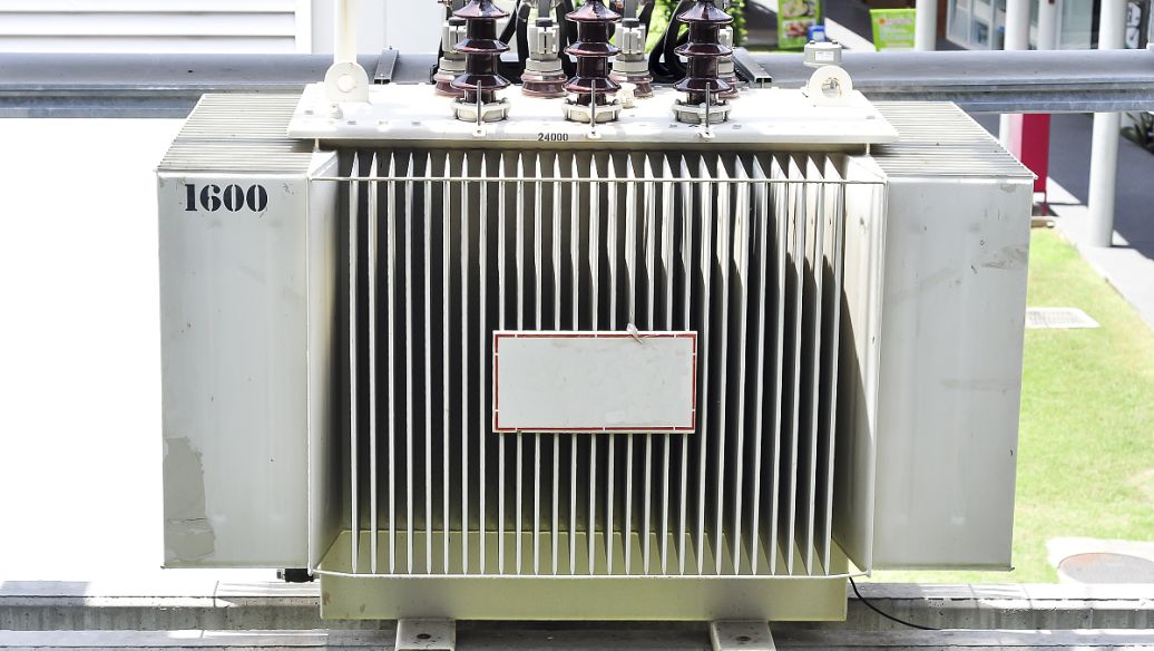
This is the transformer most people encounter in daily life, even if they never see it directly. It is inside power adapters, distribution transformers, industrial control transformers, and building power systems.
If N2 < N1, then V2 < V1. That is the defining behavior of a step-down transformer.
For example, a distribution transformer may reduce medium voltage such as 11 kV or 13.8 kV to utilization voltages like 400/230 V or 480/277 V depending on the regional system. From there, additional control or electronic power supplies may reduce voltage further to 24 V, 12 V, or 5 V.
Transformer Voltage Ratio and Turns Ratio in Step-Down Operation
The same formula applies in step-down operation:
V2 / V1 = N2 / N1
If the primary has 1000 turns and the secondary has 100 turns, the turns ratio is 10:1 from primary to secondary. If the input is 2300 V AC, the ideal output is 230 V AC.
This proportional relationship is used daily in distribution system planning, adapter design, and machine control panel engineering.
When comparing step-up and step-down operation, the formula does not change. What changes is which side has the greater number of turns and which side becomes the high-voltage side.
How Current Changes in a Step-Down Transformer
In a step-down transformer, voltage decreases and current increases approximately in inverse proportion under ideal conditions.
Using the power relation:
V1 × I1 ≈ V2 × I2
If voltage is reduced from 480 V to 120 V, the current on the secondary side can be about four times the primary current for the same power transfer, ignoring losses.
That increase in current affects conductor sizing. The lower-voltage winding often requires thicker wire because it must carry higher current.
This is a practical detail often overlooked in simple textbook summaries. Real transformer construction is not only about voltage ratio. It is also about thermal limits, copper loss, and mechanical robustness under load.
Step Up Transformer vs Step-Down Transformer Table
The fastest way to compare these two transformer types is to place their most important characteristics side by side.
Table: Difference Between Step-Up and Step-Down Transformer
| Parameter | Step-Up Transformer | Step-Down Transformer |
|---|---|---|
| Voltage level | Raises input voltage to a higher output voltage | Lowers input voltage to a lower output voltage |
| Current behavior | Secondary current decreases approximately inversely | Secondary current increases approximately inversely |
| Turns ratio | Secondary turns greater than primary turns | Secondary turns fewer than primary turns |
| Primary/secondary wire thickness | Primary may need thicker conductor due to higher current on low-voltage side | Secondary often needs thicker conductor due to higher current on low-voltage side |
| Insulation needs | Higher insulation demand on high-voltage secondary side | Higher insulation demand on high-voltage primary side |
| Efficiency | Often very high, commonly 95% to 99% depending on class and rating | Often very high, commonly 95% to 99% depending on class and rating |
| Common uses | Power transmission, X-ray systems, high-voltage testing, inverter output boosting | Distribution networks, chargers, appliances, control circuits, electronics power supplies |
| Typical installation point | Near generation or specialized high-voltage equipment | Near end users, substations, equipment panels, consumer products |
| Main goal | Reduce transmission current and enable high-voltage operation | Deliver safe, usable, equipment-compatible voltage |
Step Up Transformer vs Step-Down Transformer in Power Transmission
The clearest large-scale example of both transformer types working together is the electric grid. Utilities rely on them in sequence, not as competing devices but as complementary parts of the same system.
At the generating station, power is produced at a moderate voltage. Typical generator terminal voltages may range from around 11 kV to 25 kV depending on plant design.
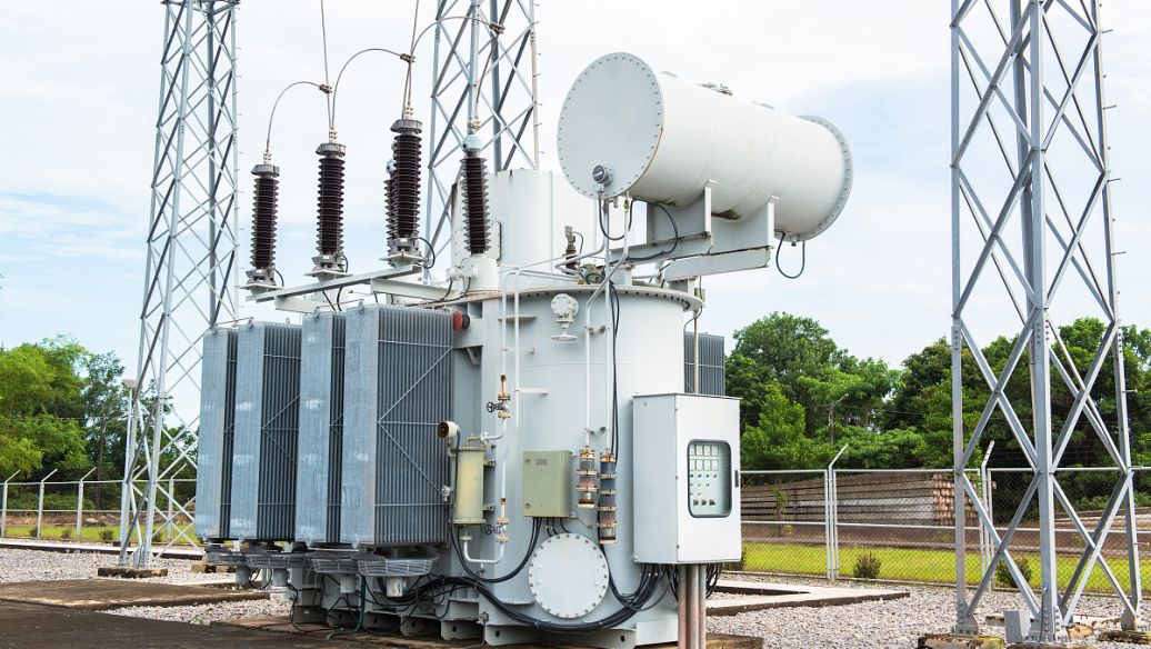
That voltage is too low for efficient long-distance bulk transmission. So utilities use step-up transformers to raise it to high transmission levels such as 110 kV, 220 kV, 400 kV, 500 kV, or higher depending on the country and network.
The reason is straightforward. For a given power level, increasing voltage reduces current. Lower current dramatically cuts conductor losses, because line loss is proportional to the square of current:
Loss = I²R
Near cities, industrial zones, and local communities, substations then use step-down transformers to reduce voltage in stages. A transmission voltage may be stepped down to sub-transmission, then to medium-voltage distribution, and finally to low-voltage service for homes and businesses.
This staged architecture is the reason modern grids can move enormous amounts of energy economically over long distances while still supplying practical voltages at the point of use.
Table: Power Transmission Transformer Comparison
| Grid Stage | Typical Voltage Example | Transformer Role | Practical Purpose |
|---|---|---|---|
| Generation output | 11 kV to 25 kV | Source voltage from generator | Power produced at plant terminals |
| Generation step-up station | 11 kV to 220 kV or 400 kV | Step-up Transformer | Reduce current and transmission losses |
| Bulk transmission network | 110 kV, 220 kV, 400 kV, 500 kV+ | High-voltage transfer | Long-distance efficient power transport |
| Primary substation | 220 kV to 66 kV or 132 kV to 33 kV | Step-Down Transformer | Transition from transmission to regional distribution |
| Local distribution substation | 33 kV to 11 kV or 13.8 kV | Step-Down Transformer | Supply feeder networks |
| Service distribution | 11 kV to 400/230 V or 13.8 kV to 480/277 V | Step-Down Transformer | Deliver usable voltage to buildings and facilities |
| End-use electronics | 230 V to 12 V, 19 V, 5 V | Step-Down Transformer or power supply stage | Operate devices safely and efficiently |
As a power transmission transformer comparison, the lesson is clear: step-up transformers make long-distance transport economical, and step-down transformers make electricity usable.
Real-World Examples of Step-Up and Step-Down Transformers
Transformer theory becomes much easier to understand when tied to equipment people actually use. The following examples reflect common industrial and commercial voltage patterns.
These are representative values. Exact voltages vary by country, equipment standard, and system design.
Table: Real-World Data and Examples
| Application | Transformer Type | Typical Input Voltage | Typical Output Voltage | Why It Is Used |
|---|---|---|---|---|
| Power plant generator station | Step-Up Transformer | 13.8 kV | 230 kV to 500 kV | Enable efficient long-distance transmission |
| Grid substation near city load center | Step-Down Transformer | 132 kV | 33 kV | Reduce transmission voltage for regional distribution |
| Pole-mounted neighborhood transformer | Step-Down Transformer | 11 kV | 400/230 V | Supply homes and small businesses |
| Mobile phone charger | Step-Down Transformer or isolated converter stage | 120 V or 230 V AC | 5 V to 20 V DC output equivalent system | Safe low-voltage charging |
| Microwave oven high-voltage section | Step-Up Transformer | 120 V or 230 V AC | Approximately 2 kV AC class | Power magnetron circuit |
| Railway traction supply | Step-Down Transformer | 132 kV or 220 kV grid supply | 25 kV traction supply | Feed overhead rail systems |
| Solar farm inverter station | Step-Up Transformer | 0.4 kV to 0.8 kV inverter output | 11 kV to 33 kV | Connect renewable generation to collection grid |
| Industrial control panel | Step-Down Transformer | 480 V AC | 120 V AC or 24 V AC | Power relays, indicators, and controls |
| X-ray machine | Step-Up Transformer | 220 V to 440 V AC range | Tens of kV | Create high voltage for imaging tube operation |
| Doorbell transformer | Step-Down Transformer | 120 V or 230 V AC | 8 V to 24 V AC | Low-voltage household signaling |
One reason customers in industrial and utility-adjacent markets pay close attention to transformer sourcing is that these examples are not interchangeable. A charger transformer, a dry-type control transformer, and a high-voltage step-up unit serve entirely different electrical and safety purposes.
That is exactly why brand expertise matters. A company like Weisho Electric is more valuable when it can connect specification details to actual use cases instead of selling “one-size-fits-all” hardware.
Step-Down Transformer Applications
Step-down transformer applications are far more visible in daily life because end users need lower voltage much more often than higher voltage.
Most buildings, appliances, electronics, and control systems depend on voltage reduction somewhere in the chain. Even when the final product contains switch-mode electronics, step-down transformation or isolation remains a key design function in the broader power path.
Consumer Electronics and Charging Systems
Consumer electronics rely heavily on reduced voltage. Household mains voltage is too high for phones, routers, laptops, smart speakers, televisions, and low-voltage control devices.
Common examples include:
Phone chargers: convert mains input to low-voltage charging output
Laptop adapters: reduce high AC supply to a manageable internal power stage
Televisions: internal power sections derive lower voltages for circuits and displays
Routers and modems: typically operate on low-voltage DC supplied through adapter systems
Doorbells: often use 8 V, 12 V, 16 V, or 24 V transformer outputs
Smart home hubs: low-voltage supply for electronics and communications modules
In many markets, the visible wall adapter has replaced the older bulky iron-core format. But the electrical need remains the same: high supply voltage must be reduced to a safe, useful level.
Industrial and Commercial Power Systems
Industrial and commercial facilities use step-down transformers everywhere, even when operators do not think of them as transformer-dependent sites.
Typical use cases include:
Control circuits: 480 V or 415 V reduced to 120 V or 24 V
Machinery panels: safer voltage for pushbuttons, relays, and contactor coils
Lighting systems: low-voltage lighting or specialty lighting circuits
Low-voltage distribution: medium-voltage feeder supply reduced for building loads
HVAC controls: thermostats and actuators often depend on reduced control voltage
Security and fire systems: alarm loops and monitoring equipment require low voltage
A practical example: in a manufacturing plant using 480 V three-phase service, individual machine control transformers commonly reduce voltage to 120 V for operator interface circuits. This improves compatibility with standard control components and can simplify maintenance.
Commercial facilities also use dry-type step-down transformers to convert 480 V to 208Y/120 V for office loads, receptacles, lighting, and information technology equipment.
Advantages and Limitations of Step-Up and Step-Down Transformers
No transformer type is universally “better.” Each is optimized for a specific electrical purpose.
The right choice depends on whether the system needs efficient high-voltage transfer or safe low-voltage utilization. Understanding both strengths and trade-offs leads to better engineering decisions.
Advantages of Step-Up Transformers
Step-up transformers are essential wherever higher voltage creates a technical or economic advantage.
Efficient long-distance transmission: higher voltage means lower current and lower line losses
Reduced conductor burden: lower current can reduce required conductor size for transmission systems
High-voltage testing: labs and specialized industries use step-up units for dielectric tests
Medical and imaging equipment: systems such as X-ray equipment require elevated voltage
Renewable integration: inverter outputs are often stepped up for grid connection
Industrial specialty processes: some furnaces, ignition systems, and electrostatic systems need elevated voltage
In utility economics, the advantage is overwhelming. A grid without step-up transformers would be drastically less efficient and significantly more expensive to build.
Advantages of Step-Down Transformers
Step-down transformers are indispensable at the point of consumption.
Safety: reduce dangerous system voltage to more usable levels
Appliance compatibility: most end-use devices require lower operating voltage
Voltage regulation: support stable supply appropriate for connected loads
Widespread deployment: used in homes, offices, plants, retail buildings, and infrastructure
Control system reliability: create standard low-voltage control levels
Isolation benefits: many designs improve separation between source and load circuits
The practical value is obvious: without step-down transformers, ordinary electrical consumption would not be safe or functional.
Limitations to Consider
Both transformer types have engineering constraints. Ignoring them leads to overheating, poor efficiency, premature failure, or unsafe installations.
Insulation demands: higher voltage requires stronger dielectric design
Core and copper losses: no transformer is lossless in real operation
Heat generation: thermal management is essential for service life
Size and weight: especially important in high-capacity or low-frequency designs
Cost: higher insulation class, better core material, and larger kVA ratings increase price
Voltage regulation: output changes with load and power factor
Harmonics and non-linear loads: can complicate design in modern electronic systems
An experienced buyer does not ask only for “the voltage.” They ask about duty cycle, ambient conditions, insulation class, frequency, installation environment, standards, and expected load behavior.
How to Choose Between a Step-Up Transformer and a Step-Down Transformer
The right transformer is chosen by working backward from the application, not by picking the cheapest catalog item.
Start with the source voltage and the required load voltage. Then consider current, load type, inrush behavior, operating frequency, installation environment, and compliance requirements.
A simple decision framework looks like this:
1. Identify the available input voltage.
2. Define the required output voltage.
3. Calculate load power in VA or kVA.
4. Estimate current on both primary and secondary sides.
5. Verify whether the application needs step-up or step-down operation.
6. Check frequency compatibility, such as 50 Hz or 60 Hz.
7. Consider insulation, cooling, enclosure, and ambient temperature.
8. Review applicable standards and safety expectations.
For example, if your facility has 480 V supply but your controls require 120 V, you need a step-down transformer. If your solar inverter output is 800 V and your collection system requires 11 kV, you need a step-up transformer.
It sounds simple, but the details matter. A transformer sized only to nominal power may still fail if the connected load has high inrush current, poor power factor, harmonic distortion, or a harsh ambient environment.
Quick Selection Checklist
Source voltage: What voltage is available at the input?
Output target: What voltage must the load receive?
Turns ratio: What winding ratio supports that voltage conversion?
kVA rating: Is the transformer sized for continuous and peak load?
Frequency: 50 Hz, 60 Hz, or special frequency?
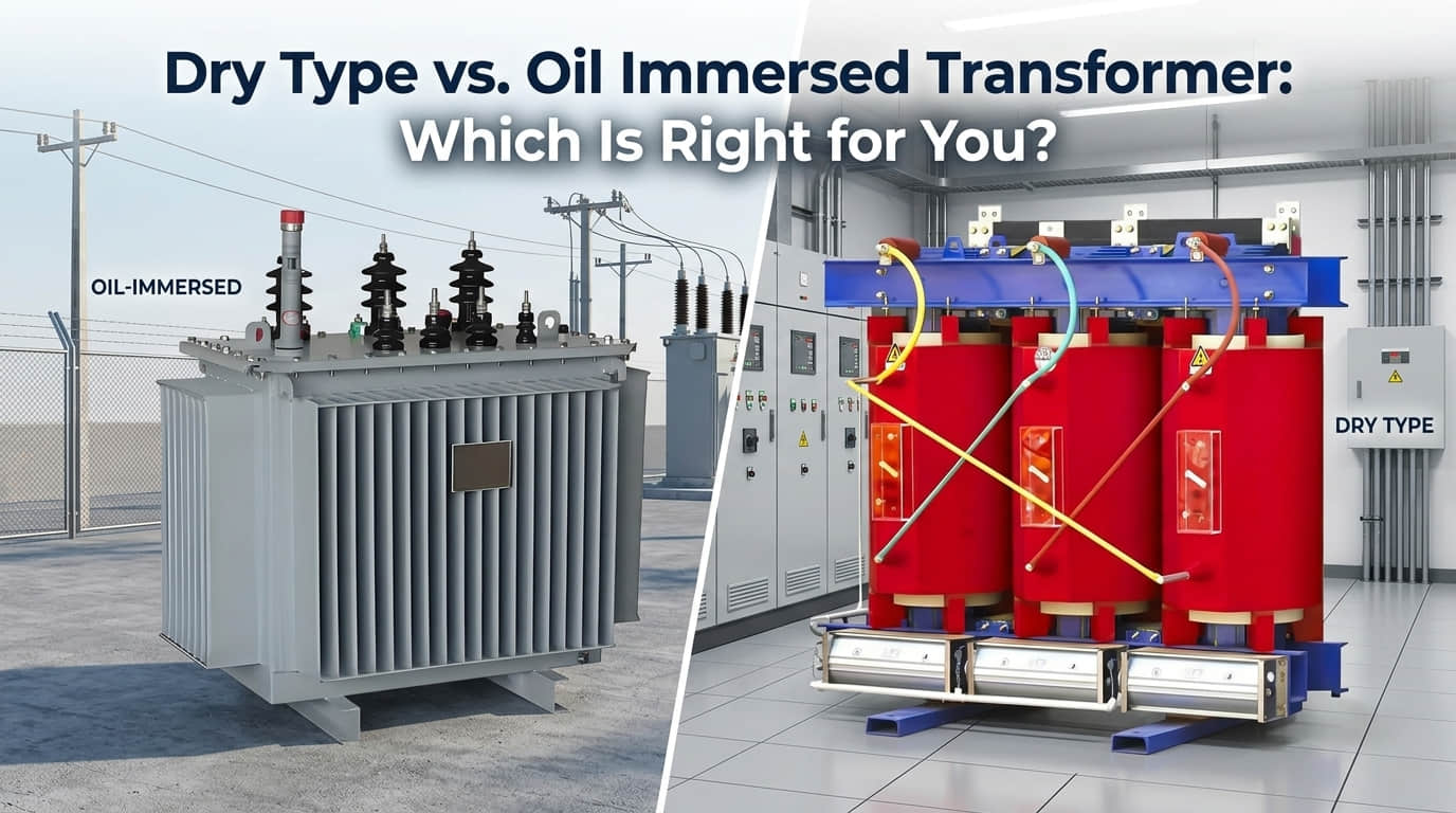
Cooling method: Air-cooled, oil-immersed, natural convection, forced cooling?
Application environment: Indoor, outdoor, high humidity, dust, corrosive site?
Insulation class: Does the design match thermal and dielectric stress?
Load type: Resistive, inductive, electronic, motor, control, or mixed?
Safety standards: Does the unit meet local and industry requirements?
Proof Through Data: Transformer Performance Metrics That Matter
A serious transformer comparison should not stop at definitions. It should look at measurable metrics.
In practice, performance depends on transformer type, rating, core material, winding design, cooling method, and installation conditions. Still, some typical ranges help buyers and engineers assess suitability.
Table: Typical Performance Data
| Application Type | Typical Efficiency | Voltage Level Range | Frequency | Insulation / Thermal Class | Load Capacity Range |
|---|---|---|---|---|---|
| Large power transmission transformer | 98% to 99.75% | 110 kV to 765 kV class systems | 50 Hz / 60 Hz | High-voltage utility class, oil-immersed systems common | 10 MVA to 1000+ MVA |
| Distribution transformer | 97% to 99% | 33 kV to 400/230 V or similar | 50 Hz / 60 Hz | Utility distribution class | 25 kVA to 10 MVA |
| Industrial dry-type transformer | 95% to 98.5% | 600 V class to several kV | 50 Hz / 60 Hz | Often Class F or Class H depending on design | 1 kVA to several MVA |
| Control transformer | 90% to 97% | 480 V to 120 V / 24 V typical | 50 Hz / 60 Hz | Industrial control insulation systems | 50 VA to 5 kVA |
| Consumer adapter / small power unit | 75% to 95% depending on topology | 120/230 V input to low-voltage output | 50 Hz / 60 Hz input systems | Compact appliance-grade insulation design | 5 W to 500 W equivalent range |
| Renewable energy step-up transformer | 97% to 99.5% | 0.4 kV to 33 kV typical plant stages | 50 Hz / 60 Hz | Outdoor or pad-mounted high-reliability class | 100 kVA to 20+ MVA |
These ranges align with common field expectations. Large power transformers can exceed 99% efficiency because even a fraction of a percent matters enormously at grid scale. Control transformers, by contrast, prioritize compactness, isolation, and inrush tolerance in addition to efficiency.
Another practical point: nameplate values alone do not tell the whole story. Real performance depends on load profile. A transformer running lightly loaded for most of its life may be affected more by no-load core losses, while a heavily loaded unit may be dominated by copper losses and thermal constraints.
FAQ
What is the main difference between a step-up transformer and a step-down transformer?
The main difference is voltage direction. A step-up transformer increases voltage and usually decreases current approximately in inverse proportion, while a step-down transformer decreases voltage and usually increases current approximately in inverse proportion. In terms of winding design, a step-up transformer has more turns in the secondary than the primary, while a step-down transformer has fewer turns in the secondary than the primary.
Where is a step-up transformer used in real life?
Step-up transformers are used in power plants, transmission systems, X-ray machines, high-voltage testing equipment, microwave oven high-voltage sections, and solar or wind energy systems that must raise output voltage before grid connection. They are especially important where efficient power transfer or specialized high-voltage operation is required.
Where is a step-down transformer used in real life?
Step-down transformers are used in substations, neighborhood distribution networks, phone chargers, laptop adapters, home appliances, industrial control panels, lighting systems, doorbells, HVAC controls, and commercial building power distribution. They are the standard choice whenever high supply voltage must be reduced to a safer and more usable level.
How does transformer voltage ratio relate to turns ratio?
The standard ideal relationship is that voltage ratio is proportional to turns ratio: V2 / V1 = N2 / N1. For example, if the secondary winding has twice as many turns as the primary winding, the ideal secondary voltage will be about twice the primary voltage. If it has half as many turns, the ideal secondary voltage will be about half the primary voltage.
Which transformer is used for long-distance power transmission?
Step-up transformers are used first for long-distance power transmission. They raise the generator voltage to a much higher level, which reduces current for the same power transfer. Lower current reduces I²R losses in transmission lines, making the system more efficient and economical.
Can a transformer both step up and step down voltage?
Yes, the function depends on winding configuration and direction of use. A transformer with two windings has a fixed turns ratio, but whether it steps voltage up or down depends on which winding is used as the input side. In practical installations, however, the transformer is usually designed, insulated, labeled, and applied for a specific intended direction and duty.
Which is safer for household devices: step-up or step-down transformer?
For household devices, step-down transformers are typically safer and more appropriate because they reduce supply voltage to levels that appliances, chargers, and electronics can use. Homes and consumer devices generally rely on lower utilization voltages, not elevated high-voltage output.
Final Takeaway and CTA
The comparison is simple in principle but powerful in practice. A Step Up Transformer is the right choice when a system needs higher voltage for efficient transmission, specialized equipment, or grid integration. A Step-Down Transformer is the right choice when a system needs safer, lower, and equipment-compatible voltage for buildings, controls, electronics, and end-use loads.
If you are comparing transformer specifications, do not stop at input and output voltage. Look at turns ratio, current behavior, kVA rating, insulation requirements, frequency, cooling method, efficiency, and application environment.
The right transformer reduces losses, protects equipment, improves safety, and lowers lifetime operating cost. The wrong one can do the exact opposite.
Need help choosing the right transformer for power transmission, industrial control, renewable energy, or low-voltage distribution?
Contact us today to compare specifications, discuss your voltage and load requirements, and get expert guidance on selecting the best step-up or step-down transformer for your exact application.